- Catalogs
- PBC Linear
- MTB-Series-Catalog
MTB-Series-Catalog
1 /6Pages

MTB-Series-Catalog
1 /6Pages
Catalog excerpts

LINEAR ACTUATOR TECHNOLOGY MT Series MTB 42 Belt Driven Linear Actuator The MT Series offers a number of profile sizes with multiple design configurations to fit almost any application. TECHNICAL DATA features & benefits • High Acceleration, Speed & Rigidity • Long Travel Length • Low Friction, Noise & Vibration • Strong yet Lightweight & Corrosion Resistant • Multiple Accessories & Options Pulley Drive Ratio Number of Pulley Teeth 0.784 1. Moment arms for calculating moments should be measured from the centerline of the extrusion. 2. Limit switches must be used in order to prevent the carriage from contacting the actuator end blocks, resulting in damage. 3. 25 mm of over-travel has been added to the body length in each direction to allow for carriage over-travel. 25 mm is the recommended over-travel; although a minimum of 10 mm may be specified for special applications. 5– T-slots for mounting and sensor mounting 2– Steel reinforced belt capable of handling high loads 4– Adjustable belt tension Base Weight 1– Anodized aluminum housing and carriage 3– Ball guided rail system Iy Max. Radial Load on Input Shaft No Load Torque For combined loads, the combined loading cannot exceed the
Open the catalog to page 1
OVERALL LENGTH = BODY LENGTH + DRIVE END LENGTH + IDLER END LENGTH = BODY LENGTH + 64 + 64 25 mm OVERTRAVEL ZONE BODY LENGTH = STROKE + CARRIAGE LENGTH + (2 x OVERTRAVEL) = STROKE + 130 + (2 x 25) 4.9 SHAFT VERSIONS FEMALE - Ø 10 mm - 12 mm MALE - Ø 12 mm (Available upon request.) Mid Section Mounting Bracket Motor Mounts/ Coupling Housings Flange Plate ORDERING INFORMATION Size (mm) (Base x Height) System Type* Body Length** Must include 50 mm over-travel MTB Belt Driven Unit Stub Shafting For lengths greater than 1,500 mm consult factory Shaft Diameter Shaft Type Guidance Type 2 = Profile rail...
Open the catalog to page 2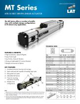
LINEAR ACTUATOR TECHNOLOGY MT Series MTB 55 Belt Driven Linear Actuator The MT Series offers a number of profile sizes with multiple design configurations to fit almost any application. TECHNICAL DATA features & benefits • High Acceleration, Speed & Rigidity • Long Travel Length • Low Friction, Noise & Vibration • Strong yet Lightweight & Corrosion Resistant • Multiple Accessories & Options Pulley Drive Ratio Number of Pulley Teeth Max RPM 1. Moment arms for calculating moments should be measured from the centerline of the extrusion. 2. Limit switches must be used in order to prevent the carriage...
Open the catalog to page 3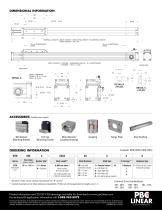
OVERALL LENGTH = BODY LENGTH + DRIVE END LENGTH + IDLER END LENGTH = BODY LENGTH + 88 + 88 25 mm OVERTRAVEL ZONE BODY LENGTH = STROKE + CARRIAGE LENGTH + (2 x OVERTRAVEL) = STROKE + 150 + ( 2 x 25) 8.4 SHAFT VERSIONS FEMALE - Ø 12 - 14 mm MALE - Ø 16 mm (Available upon request.) Mid Section Mounting Bracket Motor Mounts/ Coupling Housings Flange Plate ORDERING INFORMATION Size (mm) (Base x Height) System Type* Body Length** Must include 50 mm over-travel MTB Belt Driven Unit Stub Shafting For lengths greater than 1,500 mm consult factory Shaft Diameter Shaft Type Guidance Type 2 = Profile rail...
Open the catalog to page 4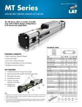
LINEAR ACTUATOR TECHNOLOGY MT Series MTB 80 Belt Driven Linear Actuator The MT Series offers a number of profile sizes with multiple design configurations to fit almost any application. TECHNICAL DATA features & benefits • High Acceleration, Speed & Rigidity • Long Travel Length • Low Friction, Noise & Vibration • Strong yet Lightweight & Corrosion Resistant • Multiple Accessories & Options Pulley Drive Ratio Number of Pulley Teeth Max RPM 1. Moment arms for calculating moments should be measured from the centerline of the extrusion. 2. Limit switches must be used in order to prevent the carriage...
Open the catalog to page 5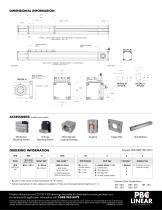
OVERALL LENGTH = BODY LENGTH + DRIVE END LENGTH + IDLER END LENGTH = BODY LENGTH + 104 + 104 BODY LENGTH = STROKE + CARRIAGE LENGTH + (2 x OVERTRAVEL) = STROKE +230 + (2 x 25) 40 SHAFT VERSIONS FEMALE - Ø 16 - 19 mm MALE - Ø 19 mm (Available upon request.) Mid Section Mounting Bracket Motor Mounts/ Coupling Housings Flange Plate ORDERING INFORMATION Size (mm) (Base x Height) System Type* Body Length** Must include 50 mm over-travel MTB Belt Driven Unit Stub Shafting For lengths greater than 1,500 mm consult factory Shaft Diameter Shaft Type Guidance Type 2 = Profile rail w/2 runner blocks per...
Open the catalog to page 6All PBC Linear catalogs and technical brochures
 PBC-Linear
2 Pages
 military & defense
4 Pages
 Target-Market---Solutions
4 Pages
 ML Catalog
48 Pages
 Cam Roller Technology Catalog
68 Pages
 Flange Mount
1 Page
 Round Shaft Technology Catalog
140 Pages
 ML serie
48 Pages
 PLA Series
2 Pages
 MTF 55-S
2 Pages
 MTE 55-L
2 Pages
 MTC 42
2 Pages
 MTD 42-Bidirectional
2 Pages
 ML Series
4 Pages
 Commercial Rail
2 Pages
 Linear Bearings and Shafting
140 Pages
 CPC Standard Profile Rail
17 Pages
 Simo Series Motor Mounts
12 Pages
 MRS Sigma
1 Page
 LAT
LAT2 Pages
 Underwater LAT Drill
2 Pages
 PLA Solar Furnace
2 Pages
 PL Series
2 Pages
 MX Series
2 Pages
 MT Series
2 Pages
 MLA Series
2 Pages
 ML Series
2 Pages
 SIMO Process Overview
1 Page
 PBC LINEAR MOTION SOLUTIONS
36 Pages


Archived catalogs
 PBC Linear Motion Catalog
204 Pages
 Miniature Slide System
2 Pages
 Mini-Rail
2 Pages
 PBC Linear Motion Catalog
260 Pages

- Lumibird electric actuator
- Nut
- Metal nut
- Lumibird compact actuator
- Lumibird screw actuator
- Lumibird linear guide
- Metal stand
- Plain bearing
- Precision actuator
- Extruded aluminum actuator
- Bearing unit
- Wheel type roller
- Stainless steel nut
- Stainless steel actuator
- Ball bearing slide
- Threaded nut
- Metal plain bearing
- Metal wheel