Flexible couplings
1 /54Pages

Flexible couplings
1 /54Pages
Catalog excerpts

Flexible couplings Innovation for your future
Open the catalog to page 1
Flexible plings 1.1 Function of a flexible coupling 3 11.1 Calculating the nominal torque to be transmitted 7 Coupling selection chart 10 JUBOFLEX WITH SEPARATE HUB 23 STRAFLEX WITH SEPARATE HUB 31 SPARE PARTS Please see current price list for availability of items. We reserve the right to modify the design and manufacture of the products and materials described in this The pictures of the products are supplied for information only. - the contract signed by both parties, or the purchase order and the acknoledgement of receipt, - eventualy, special or specific additional conditions, - sale general...
Open the catalog to page 2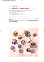
I - GENERAL I.1 - Function of a flexible coupling When transmitting torque from a drive shaft to a driven shaft, flexible couplings: • absorb and dampen irregularities in the torque, • distribute peak loads, • allow misalignments and offsets between the shafts, • permit some distortions in the mounting beds, • avoid the unwelcome constraints that may occur if a rigid coupling were fitted in the same conditions, • allow a lighter construction, with wider tolerances, and lower cost. In particular, a flexible coupling is absolutely essential if the machines that are coupled are on flexible mountings....
Open the catalog to page 3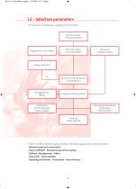
I.2 - Selection parameters The procedure for selecting a coupling is set out below: Nominal power to be transmitted Nominal torque to be transmitted Maximum rotational speed Safety coefficient Minimum nominal torque to be selected Coupling initially selected Dimensions of the shaft ends Space available Operating environment Temperature External factors Coupling finally selected In order to select a flexible coupling, therefore, the following parameters should be known: • Nominal torque to be transmitted. • Safety coefficient - Nominal torque of the coupling. • Stiffness - Misalignments - Offset....
Open the catalog to page 4
I.2.1 - NOMINAL TORQUE TO BE TRANSMITTED The nominal torque is the main factor which determines the dimensions of the coupling between the shafts of the machines that are connected directly to it. The nominal torque to be transmitted is a function of the nominal power to be transmitted and the rotational speed. 7 024 x P (bhp) T (N.m) = __________________ N (rpm) 9 550 x P (Kw) T (N.m) = __________________ N (rpm) The nominal power to be transmitted is that of the driving machine expressed in kilowatts (Kw) or brake horsepower (bhp). The couplings in PAULSTRA's standard range can transmit power...
Open the catalog to page 5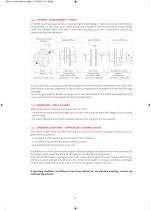
I.2.3 - STIFFNESS - MISALIGNMENTS - OFFSETS A flexible coupling always allows, to varying degrees depending on type, structure and dimensions, displacements in four ways: axial, radial, conical and torsional. A stiffness defined for each of these cases. The stiffness affects the way in which the coupling reacts when subjected to each of the various possible displacements. Torsional or polar stiffness Radial stiffness Axial stiffness Conical stiffness Cθ Torque Cθ Kθ = __________ = ___ Angular Θ expressed in m.kN/radian Fy Radial force Fy Ky = ________________ = ___ Corresponding Y radial displacement...
Open the catalog to page 6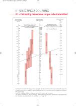
II - SELECTING A COUPLING II.1 - Calculating the nominal torque to be transmitted Nominal power to be transmitted BhP/Kw WELL ALIGNED MACHINES SLIGHT IRREGULARITIES Ex: electric motor and rotating pump SAFETY COEFFICIENT 1 ALIGNED MACHINES AVERAGE IRREGULARITIES Ex: Internal combustion engine, balanced and geared SAFETY COEFFICIENT 2 Nominal torque to be transmited N.m Example: To calculate the torque, draw a straight line between the points representing the power to be transmitted and the rotational speed of the machine. The intersection at the central scale indicates the torque value. Ex.:...
Open the catalog to page 7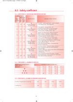
II.2 - Safety coefficient II.2.1 - COEFFICIENT K1 = DRIVING MACHINE/DRIVEN MACHINE Driving Machine Piston Engine Electr. motor 4 to 6 1 to 3 or turbine cylin. cylin. 1 Driven machine Examples of driven machines • Lay shaft • Lighting generator • Series of shafts • Centrifugal pump • Centrifugal fan... Smooth operation Very low inertia Irregular operation Low inertia • Fluid agitator • Conveyor belt • Lift • Rotating machine tools for wood and metal • Light textile machines • Folding machines • Geared pumps • Paddle pumps • Fans... Irregular operation Average inertia • Agitator for heavy liquid...
Open the catalog to page 8
II.2.4 - NOMINAL TORQUE OF THE COUPLING Nominal torque of the coupling = Nominal torque to be transmitted x safety coefficient. The safety coefficient, K, is the product of the three coefficients K1, K2 and K3. The above parameters should enable one or two types of coupling to be selected which are suitable for the application required. The final choice will be made on the basis of the data sheets for the coupling selected, checking: • The dimensions allowed for the shaft ends. • The space available. • The exact values of the misalignements, offset, stiffness. • And any other parameter (eg: installation)....
Open the catalog to page 9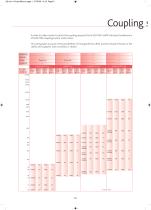
In order to make it easier to select the coupling required, this SELECTION CHART indicates the behaviour of PAULSTRA couplings when under stress. This rating takes account of the possibilities of misalignments, offset and the resultant forces on the shafts and supports. Each condition is shown: .. Nominal Speed * separate hubs
Open the catalog to page 10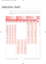
selection chart Very flexible More precise information on the values for misalignment, offset and rigidity can be found in the individual Data Sheets. TORSION RADIAL AXIAL CONICAL Braking force proportional to the speed of displacement. * See current price list for items held in stock.
Open the catalog to page 11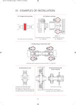
III - EXAMPLES OF INSTALLATION III.1 Flanged shaft mounting The most common mounting Mounted directly on flywheel Ex. : AXOFLEX Spacer Mounting with spacer. Ex. : JUBOFLEX III.3 Mounting on transmission shaft Assembly with centred transmission shaft. Ex.: JUBOFLEX III.5 Drum brake and disk brake mounting Increases the flexibility while keeping the torque constant. Ex.: AXOFLEX coupling with two sets of studs linked by an “anti-centrifuge” disk. Disk brake mounting Drum brake for mounting our couplings with rings: AXOFLEX, RTP
Open the catalog to page 12All PAULSTRA catalogs and technical brochures
 STRAFLEX®
2 Pages
 JUBOFLEX® TYPE S
2 Pages
 JUBOFLEX®
2 Pages
 MPP®
MPP®4 Pages
 MINIFLEX®
4 Pages
 V402-MG
2 Pages
 V43 / V44 / V45 / V46
2 Pages
 POLYURETHANE FOAM
2 Pages
 VIBSOL ®
2 Pages
 METALLIC CUSHIONS
4 Pages
 PAULSTRADYN®
4 Pages
 RADIAFLEX®
4 Pages
 GENERAL CATALOGUE INDUSTRY
380 Pages
 Dynamic sealing
35 Pages
 Flexible Mounts
164 Pages
 Flexible Bushes
22 Pages
 Metal Mounting
74 Pages


