- Catalogs
- Pasternack Enterprises, Inc.
- 60 GHz Receiver (Rx) Waveguide Module
60 GHz Receiver (Rx) Waveguide Module
1 /18Pages

60 GHz Receiver (Rx) Waveguide Module
1 /18Pages
Catalog excerpts

60 GHz Receiver (Rx) Waveguide Module TECHNICAL DATA SHEET The PEM002 is a highly integrated millimeter wave receiver that covers the 60 GHz global unlicensed spectrum allocations packaged in a standard waveguide module. Receiver architecture is a double conversion, sliding IF with wide bandwidth capability through the conversion chain down to baseband. The I/Q analog interface along with built-in AM and FM detectors provides for flexibility in design and applications. The receiver incorporates a complete waveguide interface with low-loss transition between the chip and the WR15 waveguide port. The integrated package is small and lightweight, with a simple to use multi-pin ST4 connector for power, reference clock, digital control port and baseband signals. Either of two reference clocks can be used for setting 540 MHz or 500 MHz channel spacing. Complete millimeter wave receiver WR-15, UG-385/U flange Operates in the 57 to 66 GHz unlicensed band 6 dB noise figure Up to 1.8 GHz modulation bandwidth I/Q analog baseband interface Integrated AM/ASK and FM/FSK detectors On chip synthesizer covers 57 to 64.8 GHz 500 MHz or 540 MHz step size 285.714 MHz clock for 500 MHz step size 308.572 MHz clock for 540 MHz step size Power, control, signals on ST4 connector Temperature sensor 802.11ad: 58.32, 60.48, 62.64, 64.80 GHz 802.11aj: 59.94, 61.02, 62.10, 63.18 GHz Any Channel (500 MHz or 540 MHz) 57-64.8 GHz Multi-Gbps Digital Communications HD Video Transmission Millimeter Wave Radar Millimeter Wave Radiometry Millimeter Wave Imaging Microwave Temperature Profiling (MTP) Development for 802.11ad and 802.11aj ATE Equipment for 60 GHz Manufacturing Test Click the following link (or enter part number in “SEARCH” on website) to obtain additional part information including price, inventory and certifications: 60 GHz Rec
Open the catalog to page 1
The information contained in this document is accurate to the best of our knowledge and representative of the part described herein. It may be necessary to make modifications to the part and/or the documentation of the part, in order to implement improvements. Pasternack reserves the right to make such changes as required. Unless otherwise stated, all Pasternack Enterprises, Inc. • P.O. Box 16759, Irvine, CA 92623 [email protected] * [email protected] ©2013 Pasternack Enterprises All Rights Reserved
Open the catalog to page 2
The information contained in this document is accurate to the best of our knowledge and representative of the part described herein. It may be necessary to make modifications to the part and/or the documentation of the part, in order to implement improvements. Pasternack reserves the right to make such changes as required. Unless otherwise stated, all Pasternack Enterprises, Inc. • P.O. Box 16759, Irvine, CA 92623 [email protected] * [email protected] ©2013 Pasternack Enterprises All Rights Reserved
Open the catalog to page 3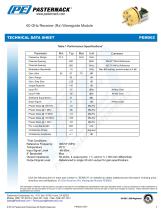
60 GHz Receiver (Rx) Waveguide Module TECHNICAL DATA SHEET PEM002 Table 1 Performance Specifications* Frequency Range Channel Spacing Channel Spacing Modulation Bandwidth Gain, Max Gain, Range Gain, Step Size Image Rejection Sideband Suppression Noise Figure *Test Conditions: Reference Frequency Temperature Input Signal Level IF Bandwidth Output Impedance Output Signal Level 308.571 MHz 25°C -65 dBm Max 50 ohms, 4 output ports: I +/- and Q +/- (100 ohm differential) Referenced to single 50 ohm output for gain specifications Click the following link (or enter part number in “SEARCH” on website)...
Open the catalog to page 4
60 GHz Receiver (Rx) Waveguide Module TECHNICAL DATA SHEET PEM002 Table 2 Recommended Operating Conditions Description Power Supplies Serial Control Port Logic High Serial Control Port Logic Low Serial Control Port Speed Operating Temperature Reference clock power level specified at 100 ohms differential 2 Baseband voltage at each of the 4 baseband outputs (I +/-, Q +/-) 3 Temperature sensor is a 2N3904 NPN transistor die connected as a diode junction Click the following link (or enter part number in “SEARCH” on website) to obtain additional part information including price, inventory and certifications:...
Open the catalog to page 5
60 GHz Receiver (Rx) Waveguide Module TECHNICAL DATA SHEET PEM002 Table 3 Absolute Maximum Ratings Description Power Supplies DATA CLOCK SCANOUT DATA Reference Clock Serial Control Port Logic Low Serial Control Port Logic High Power Dissipation Storage Temperature Assertion of RESET, active high, asynchronously resets all registers Click the following link (or enter part number in “SEARCH” on website) to obtain additional part information including price, inventory and certifications: 60 GHz Receiver (Rx) Waveguide Module PEM002
Open the catalog to page 6
60 GHz Receiver (Rx) Waveguide Module TECHNICAL DATA SHEET Receiver Architecture The PEM002 receiver uses a double conversion superheterodyne architecture with a sliding IF. The IF frequency is at 1/7 the RF carrier frequency, and the VCO is at 2/7 the RF carrier frequency. The LO is 3x the VCO frequency. The LO and IF are generated from a built-in synthesizer that has a step size at the RF carrier frequency of either 500 MHz or 540 MHz depending upon which reference clock frequency is used. The 540 MHz step size uses a 308.571 MHz reference, and the 500 MHz step uses a 285.714 MHz frequency....
Open the catalog to page 7
60 GHz Receiver (Rx) Waveguide Module TECHNICAL DATA SHEET Synthesizer Design The PEM002 receiver uses a double conversion superheterodyne architecture with a sliding IF. The IF frequency is at 1/7 the RF carrier frequency, and the VCO is at 2/7 the RF carrier frequency. The LO is 3x the VCO frequency. The tables below show the RF carrier, IF, VCO and LO for the frequency range from 57 GHz to 64.80 GHz at 540 MHz and 500 MHz channel spacing respectively. The reference clock for the synthesizer at 540 MHz spacing is 308.571 MHz; for 500 MHz spacing it is 285.714 MHz. The loop bandwidth of the...
Open the catalog to page 8
60 GHz Receiver (Rx) Waveguide Module TECHNICAL DATA SHEET Digital Control Registers and Serial Interface Protocol - Write Operation The PEM002 is configured via the serial control port which transfers data synchronously to or from (write or read operation) a register location. Register locations are organized into 16, byte-wide (8-bit) locations. The register locations are written to or read from one byte at a time as shown in Figures 5 and 6 respectively. Figure 5 shows the sequence of the digital control signals for the ENABLE, CLOCK and DATA input pins (ST4 connector, pins 39, 36 and 38 respectively)...
Open the catalog to page 9All Pasternack Enterprises, Inc. catalogs and technical brochures
 PE2209-6
6 Pages
 PE2203-10
3 Pages
 PE2201-20
6 Pages
 PE2201-30
6 Pages
 PE85N1001
6 Pages
 PE1V11007
8 Pages
 PE91166
3 Pages
 PE91165
3 Pages
 PE9748
3 Pages
 PE9746
4 Pages
 PE9745
3 Pages
 PE9679
2 Pages
 PE9678
5 Pages
 PE9677
4 Pages
 PE9676
4 Pages
 PE9659
5 Pages
 PE9658
4 Pages
 PE9657
4 Pages
 PE9652
3 Pages
 PE9651
3 Pages
 PE9650
4 Pages
 PE9649
3 Pages
 PE9332
4 Pages
 PE9331
5 Pages
 PE9330
4 Pages
 PE9326
4 Pages
 PE9325
4 Pages
 PE9324
4 Pages
 PE9323
3 Pages
 PE9322
4 Pages
 PE9321
4 Pages
 PE91294
3 Pages
 PE91293
3 Pages
 PE91292
3 Pages
 PE91291
3 Pages
 PE91171
3 Pages
 PE91170
3 Pages
 PE91169
3 Pages
 PE91144
3 Pages
 PE9648
4 Pages
 PE9647
4 Pages
 PE9644
4 Pages
 PE9437
4 Pages
 PE91164
3 Pages
 PE91163
3 Pages
 PE91162
3 Pages
 PE91161
3 Pages
 PE91136
4 Pages
 PE91113
5 Pages
 PE91112
4 Pages
 PE91111
4 Pages
 PE91110
4 Pages
 PE91070
5 Pages
 PE91011
4 Pages
 PE91010
4 Pages
 PE91009
4 Pages
 PE91008
4 Pages
 PE9782
3 Pages
 PE9781
3 Pages
 PE9769
3 Pages
 PE9767
3 Pages
 PE9766
3 Pages
 PE9668
4 Pages
 PE9667
4 Pages
 PE9666
4 Pages
 PE9665
3 Pages
 PE9664
3 Pages
 PE9663
4 Pages
 PE9662
4 Pages
 PE9661
4 Pages
 PE9660
4 Pages
 PE9646
5 Pages
 PE9645
4 Pages
 PE9461
4 Pages
 PE9460
4 Pages
 PE9457
3 Pages
 PE9456
3 Pages
 PE9455
4 Pages
 PE9454
5 Pages
 PE9438
4 Pages
 PE9436
3 Pages
 PE91298
3 Pages
 PE91297
3 Pages
 PE91296
3 Pages
 PE91295
3 Pages
 PE91168
5 Pages
 PE91167
3 Pages
 PE91128
3 Pages
 PE91127
4 Pages
 PE91126
4 Pages
 PE91125
4 Pages
 PE91124
3 Pages
 PE91060
4 Pages
 PE91146
3 Pages
 PE91145
3 Pages
 PE9656
3 Pages
 PE9655
4 Pages
 PE9654
4 Pages
 PE9653
4 Pages
 PE9640
4 Pages
 PE9452
4 Pages
 PE91160
3 Pages
 PE91159
3 Pages
 PE91158
3 Pages
 PE91157
3 Pages
 PE91148
3 Pages
 PE91138
4 Pages
 PE9675
4 Pages
 PE9674
4 Pages
 PE9673
4 Pages
 PE9672
4 Pages
 PE9504
4 Pages
 PE9503
4 Pages
 PE9502
4 Pages
 PE9501
4 Pages
 PE9459
3 Pages
 PE9458
3 Pages
 PE9453
4 Pages
 PE9451
4 Pages
 PE91139
4 Pages
 PE91137
4 Pages
 PE91123
4 Pages
 PE91122
4 Pages
 PE91121
4 Pages
 PE91120
4 Pages
 PE91055
4 Pages
 PE91048
3 Pages
 PE9757
3 Pages
 PE9756
3 Pages
 PE9755
3 Pages
 PE9754
3 Pages
 PE9753
3 Pages
 PE9752
3 Pages
 PE9751
3 Pages
 PE9750
3 Pages
 PE9729
3 Pages
 PE9728
4 Pages
 PE9727
4 Pages
 PE9726
4 Pages
 PE9715
4 Pages
 PE91119
3 Pages
 PE91118
3 Pages
 PE91109
4 Pages
 PE91108
3 Pages
 PE91086
4 Pages
 PE9765
3 Pages
 PE9764
3 Pages
 PE9763
3 Pages
 PE9762
3 Pages
 PE9747
4 Pages
 PE9721
4 Pages
 PE9720
4 Pages
 PE9719
3 Pages
 PE9718
3 Pages
 PE9717
3 Pages
 PE9716
3 Pages
 PE91115
4 Pages
 PE91085
4 Pages
 PE91084
5 Pages
 PE9693
3 Pages
 PE9692
3 Pages
 PE9691
3 Pages
 PE9690
3 Pages
 PE9881-34
3 Pages
 PE9881-24
4 Pages
 PE9881-20
2 Pages
 PE-W15A001
2 Pages
 PEM004
7 Pages
 RF Attenuator Catalog Pasternack
35 Pages
 Waveguides
38 Pages
 RF Tappers Catalog Pasternack
16 Pages
 RF Switches Catalog Pasternack
26 Pages
 RF Diplexers Catalog Pasternack
15 Pages
 RF Limiters Catalog Pasternack
15 Pages
 RF Filters Catalog Pasternack
18 Pages
 RF Detectors Catalog Pasternack
16 Pages
 RF DC Blocks Catalog Pasternack
16 Pages
 RF Connectors Catalog Pasternack
72 Pages
 RF Bias Tees Catalog Pasternack
15 Pages
 RF Amplifiers Catalog Pasternack
23 Pages
 RF Baluns Catalog Pasternack
15 Pages
 RF Adapters Catalog Pasternack
55 Pages


Archived catalogs
 Pasternack RF Product Guide 2016
272 Pages
 BNC Male to BNC Male Adapter
3 Pages
 LC Male to HN Female Adapter
2 Pages
 N Female to MCX Plug Adapter
2 Pages
 PE5200
2 Pages
 MCX Plug to BNC Male Adapter
2 Pages
 N Female to MCX Jack Adapter
2 Pages
 MICROWAVE SYSTEMS
3 Pages
 PE5201
2 Pages
 Waveguide Power Amplifiers -
5 Pages
 SMA High Power Limiter
7 Pages
 LMR ® -100A
2 Pages
 LMR ® -195
2 Pages
 LMR ® -400-LLPL
3 Pages
 PE6000-75
1 Page
 PE6035
3 Pages
 PF6045
1 Page
 PE6061-50
1 Page
 PE6063-93
1 Page
 PE-W22CP001-20
6 Pages
 PEWCP1010
5 Pages
 PEWCP1074
5 Pages
 PE38134-YW
1 Page
 PE51006
1 Page
 PE38135-YW
1 Page
 PE38133-BK
1 Page
 PE38134-WH
1 Page
 PE7212-3
3 Pages
 PE7330-30
3 Pages
 PE7386-10
5 Pages
 PE7385-6
5 Pages
 PE7412-6
3 Pages
 PE3CA1103
4 Pages
 PE2205-20
6 Pages
 PE11S3904
8 Pages
 PE6137
3 Pages
 PE6199
3 Pages
 PE6074
2 Pages
 Pasternack Fiber Optic Products
18 Pages
 Pasternack RF Waveguides
21 Pages
 Pasternack RF Switches
17 Pages
 Pasternack Antennas
31 Pages
 Pasternack RF Attenuators
37 Pages
 Pasternack RF Coaxial Cables
19 Pages
 Pasternack RF Adapters
61 Pages
 Pasternack RF Connectors
79 Pages
 Pasternack RF Cable Assemblies
70 Pages
 Pasternack RF Tools
21 Pages
 Catalog 2012B - RF Tools
14 Pages
 Catalog 2012B - Fiber Optics
9 Pages
 Catalog 2012B - Waveguides
14 Pages
 Catalog 2012B - Antennas
22 Pages
 Catalog 2012B - RF Switches
11 Pages
 Catalog 2012B - RF Attenuators
20 Pages
 Catalog 2012B - RF Cables
17 Pages
 Catalog 2012B - RF Connectors
58 Pages
 Catalog 2012B - RF Adapters
58 Pages
 Catalog 2012A - New Products
35 Pages
 Catalog 2012A - Cable Assemblies
127 Pages
 Catalog 2012A - RF Connectors
74 Pages
 Catalog 2012A - RF Adapters
56 Pages
 Catalog 2012A - Coaxial Cable
10 Pages
 Catalog 2012A - RF Attenuators
17 Pages
 Catalog 2012A - RF Terminations
11 Pages
 Catalog 2012A - RF Switches
9 Pages
 Catalog 2012A - RF Waveguides
12 Pages


- Electrical cable
- Transformer
- Metal connector
- Copper cable
- Dry transformer
- Surge protector
- Round connector
- Electrical rotary joint
- Single-pole switch
- Socket electrical connector
- IP67 connector
- Insulated cable
- Circular connector
- Rectangular connector
- Male connector
- Technology switch
- Flexible cable
- Torque wrench
- Portable analyzer