- Catalogs
- Pascal Engineering Inc.
- air Work clamping system
- Products
- Catalogs
- News & Trends
- Exhibitions
air Work clamping system
1 /130Pages

air Work clamping system
1 /130Pages
Catalog excerpts
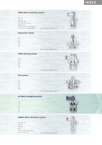
INDEX 7MPa Work clamping system CTU CTT CLU CLT CNA CMC CMD CSU CST CSN CSY CSK CEK CEA CVH VCB VCP VHD VRG VEF WPB WPC HCD HCS HCT X63 WRA WRB Refer to separate catalog for details. Expansion clamp CGC CGT CGU CGE CGY Refer to separate catalog for details. 7MPa Sensing clamp CTM CTN CLM CLN CNB Refer to separate catalog for details. Pal system CPC CPH CPY CPK WVP Refer to separate catalog for details. air Work clamping system CTX CTY CLX CLY CSS CSX 35MPa Work clamping system CTK CTW CTV CLW CLV CSW CSV WVP VCB VCP VHD VRG VEF WPC HCD HCS HCT X63 Refer to separate catalog for details.
Open the catalog to page 1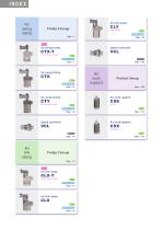
Product lineup boost model Speed controller 3 point sensor model Double acting Page → 7 Product lineup Page → 109 Dual cylinder model Speed controller Spring lift Product lineup Page → 59 3 point sensor model air Double acting Page → 63
Open the catalog to page 2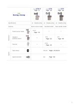
Specifications Features Double acting Built-in sensor model Double acting Dual cylinder model Double acting Standard model Standard (without sensor) Taper sleeve Speed controller
Open the catalog to page 5
Sensing Air swing clamp 3 point sensor model CTX-T 3 point sensor model Structure, Pneumatic circuit diagram …………………………………………… 7 Specifications ………………………………………………………………………… 8 Piping Performance table ………………………………………………………………… 10 Swing speed adjustment ………………………………………………………… 11 PAL sensor function and structure ……………………………………………… 12 Sensor signal detection
Open the catalog to page 6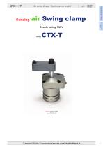
3 point sensor model air Swing clamp Double acting 1 MPa Double acting Sensing Air swing clamp CTX-T 3 point sensor model 3 point sensor model model To download CAD data / To get updated information, visit www.pascaleng.c
Open the catalog to page 7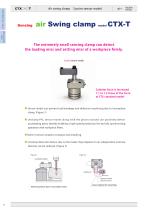
3 point sensor model Double acting CTX-T 3 point sensor model Sensing Air swing clamp The extremely small sensing clamp can detect the loading miss and setting miss of a workpiece firmly. 3 point sensor model Cylinder force is increased 1.1 to 1.3 times of the force of CTX standard model ● Sensor model can prevent tool breakage and defective machining due to incomplete clamp. (Figure 1) ● Unclamp PAL sensor moves along with the piston rod and can positively detect unclamping point, thereby enabling a high-speed production line by fully synchronizing operation with workpiece lifters. ● Built-in...
Open the catalog to page 8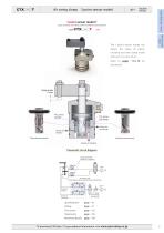
3 point sensor model Double acting Sensing Air swing clamp 3 point sensor model T Clamp, Unclamp, Over clamp stroke (Incomplete clamp) detection The 3 point sensor model can CTX-T 3 point sensor model detect the status of clamp, unclamp and over clamp stroke with just 2 circuits of air. Refer to pages →12‒15 for the details. Sensor air (clamp) Clamp detection groove Unclamp detection groove Pneumatic circuit diagram Speed controller model VCL (option) Air sensor unit (The circuit diagram is subject to change according to the model of sensor.) Mounting details To download CAD data / To get updated...
Open the catalog to page 9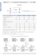
3 point sensor model Double acting Swing direction (when clamping) C. CTX-T 3 point sensor model Sensing Air swing clamp T : 3 point sensor model Clamp, Unclamp, Over clamp stroke (Incomplete clamp) detection Cylinder force (air pressure 0.5MPa) Cylinder inner diameter Effective area Swing angle Positioning pin groove position accuracy Repeated clamp positioning accuracy Full stroke Clamp stroke Over clamp stroke Cylinder capacity Mass Recommended tightening torque of mounting screws Recommended tightening torque of cap screw ● Pressure range:0.2‒1 MPa ● Oil supply:Not required 1:ISO R898 class...
Open the catalog to page 10
3 point sensor model Double acting Sensing Air swing clamp Manifold piping When choosing manifold piping, a speed controller When choosing G port piping, remove plugs. (O-ring model VCL is mountable on the G ports of the clamp. must be used.) The one touch fitting or the speed controller with one touch fitting should be mounted CTX-T 3 point sensor model Manifold piping and G port piping are available. when choosing G port piping. One touch fitting Air pressure (2 circuits) O-ring O-ring Speed controller model VCL Page →56 Speed controller Speed controller To download CAD data / To get updated...
Open the catalog to page 11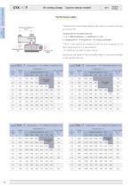
3 point sensor model Double acting Performance table Clamping force varies depending on the clamp arm length (LH) and CTX-T 3 point sensor model Sensing Air swing clamp air pressure (P). Clamping force calculation formula F = P × 1000/(Coefficient 1 + Coefficient 2 × LH) F:Clamping force P:Air pressure CTX50-T with clamp arm length (LH) 60 mm at air pressure of 1.0 MPa, Clamping force F is calculated by Clamping force F (N) Do not use the clamp in the nonusable range. It may cause damage to the cylinder and rod. Clamping force Clamping force Air pressure MPa Clamping force Clamping force F=P×1000/(0.354+0.000835×LH)...
Open the catalog to page 12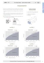
3 point sensor model Double acting Sensing Air swing clamp Swing speed adjustment Swing time is restricted by the mass and length of the clamp arm (moment of inertia) since the 90°swing action impacts the cam shaft. 1. Calculate the moment of inertia according to the arm length and mass. 2. Adjust swing speed with speed controller to ensure that 90°swing time of the clamp arm is greater than the shortest swing time in the graph shown below. CTX-T 3 point sensor model I : Moment of inertia (kg·m 2) m : Mass (kg) ● The cam groove may be damaged in case the swing speed is set at the nonusable range...
Open the catalog to page 13All Pascal Engineering Inc. catalogs and technical brochures
 Pascal auto coupler
60 Pages
 Pascal mold change system
68 Pages
 Mold clamping system
136 Pages
 Press machine system
48 Pages
 Stamping die clamping system
254 Pages
 Pascal N2 gas springs
28 Pages
 mini Gas springs
40 Pages
 N2 gas springs
86 Pages
 Pascal Products Introductions
76 Pages
 Expansion clamp
142 Pages
 35MPa Work clamping system
177 Pages
 Pal system
106 Pages
 7MPa Work clamping system
256 Pages
 Pascal mag clamp
72 Pages
