
- Catalogs
- Parker Tube Fittings Division
- Parker Hydraulic Tube Bender, Model HB632 Operation Manual--Bul. 4391-B26


Parker Hydraulic Tube Bender, Model HB632 Operation Manual--Bul. 4391-B26

Parker Hydraulic Tube Bender, Model HB632 Operation Manual--Bul. 4391-B26
The Parker Model HB632 Hydraulic Tube Bender is designed for bending annealed steel and stainless steel tubing with diameters from 3/8" to 2". It operates with a separate power source producing 10,000 psi hydraulic pressure and can be used with or without mandrels.
- Tube size range: 3/8" to 2"
- Bend radius: Minimum 1-1/8", Maximum 12" (special order)
- Maximum bend angle: 180°
- Weight: 170 lbs. without accessories
- Tube wall thickness: Minimum 4% with mandrel, 7% without mandrel
The bender features a cast aluminum housing with a hydraulically actuated drive mechanism for smooth bends up to 180°.
Model HB632 is identified by model code C, with a tubing O.D. capacity of 1/4" to 2" and a rated torque of 52,000 in./lbs.
- Securely mount the bender on a table.
- Connect the pump using the specified hose assembly.
- Select and install the appropriate radius block.
- Mark the tube for the desired bend length.
- Select the correct slide and clamp block grooves for the tube diameter.
- Position and clamp the tube securely.
- Use the tie bar for tubes over 1" O.D. or when mandrel bending.
- Set the desired bend angle, accounting for spring-back.
- Start the pump to bend the tube, ensuring proper slide block positioning.
Includes mandrel rods, mandrel rod stop assembly, universal side angle indicator, and various radius blocks for different tube sizes.
Regular maintenance is required for optimal performance. Troubleshooting guidelines are provided for common issues.
The document outlines warranty terms and conditions under the "Offer of Sale" provisions.
This document provides detailed instructions and specifications for the Parker Hannifin Hydraulic Tube Bender, including procedures for bending tubes, mandrel usage, maintenance, and warranty information.
- Bending Process: Step-by-step process for bending tubes, emphasizing mandrel use for thin-wall tubing to prevent defects.
- Mandrel Usage: Necessary for tubes with wall thicknesses between 4-6% of the tube's outer diameter. Specifications for mandrel rods and alignment are provided.
- Installation Steps: Detailed instructions for installing and adjusting the mandrel rod stop assembly, selecting the appropriate radius block, and inserting the tube for bending.
- Parts Schematic: Comprehensive list of parts for the slide arm and clamp arm assemblies, with part numbers and quantities.
- Maintenance: Regular lubrication of the king pin bearings and roller chain is recommended, along with periodic checks for hydraulic leaks.
- Warranty: The bender is warranted against defects for one year from the date of sale. Alterations void the warranty.
- Troubleshooting: Common issues such as the bender not rotating or tubes slipping are addressed with probable causes and solutions.
The document outlines the terms and conditions of sale, including pricing, shipment, warranty disclaimers, and limitations of liability.
The document outlines the responsibilities of both the Seller and Buyer regarding product specifications and data. The Buyer is responsible for ensuring that the data and specifications provided are suitable for their applications. The Seller is not liable for any loss or damage to the Buyer's property after two years without orders.
A charge may be imposed for special tooling, which remains the Seller's property. The Seller retains a security interest in all delivered products to secure payment.
The Buyer must indemnify the Seller against losses arising from improper use or specification of products. The Seller is not liable for intellectual property infringement except under specific conditions.
Orders cannot be canceled or modified without the Seller's consent. The Seller is not liable for delays due to force majeure events.
The Seller can terminate the agreement with notice. The agreement is governed by Ohio law, with disputes resolved in Cuyahoga County courts.
The Buyer must comply with relevant laws, including anti-bribery and anti-corruption laws. Contact information for Parker Hannifin Corporation and its divisions is provided.
Catalog excerpts

Hydraulic Tube Bender Model HB632 Bulletin 4391-B26
Open the catalog to page 1
Hydraulic Tube Bender Table of Contents WARNING FAILURE OR IMPROPER SELECTION OR IMPROPER USE OF THE PRODUCTS AND/OR SYSTEMS DESCRIBED HEREIN OR RELATED ITEMS CAN CAUSE DEATH, PERSONAL INJURY AND PROPERTY DAMAGE. This document and other information from Parker Hannifin Corporation, its subsidiaries and authorized distributors provide product and/or system options for further investigation by users having technical expertise. It is important that you analyze all aspects of your application and review the information concerning the product or system in the current product catalog. Due to the variety...
Open the catalog to page 2
Hydraulic Tube Bender Introduction Parker Hydraulic Tube Bender Model HB632 For 3/8" – 2" (10-50mm) tubing and 3/8 to 1-1/2 IPS Pipe The Parker Model HB632 Tube Bender is a hydraulically operated bender for bending annealed steel and stainless steel tubing from 3/8" O.D. through 2" O.D. It is operated by means of a separate power source producing 10,000 psi hydraulic pressure. It can be operated without bolting to a table or bench if no mandrels are required, making it an excellent unit to move about and use at the point where the tubing installation is being made. It can also be attached to...
Open the catalog to page 3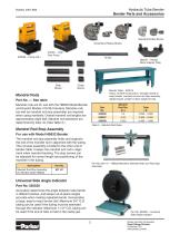
Hydraulic Tube Bender Bender Parts and Accessories Standard Radius Blocks Close Bend Radius Blocks 974691 – High Flow Pump Slide Blocks Clamp Blocks 660221 – Radius Block Adapter Plate Bender Table – 520515 Heavy, all steel construction, strongly braced to keep bender, mandrel rod and rod stop assembly rigidly braced. Length 10 feet; weight 421 lbs. Mandrel Rods Part No. — See table Mandrel rods are for use with the HB632 Model Bender and Exactol Models 412/424 benders. Mandrel rods (as well as mandrel rod stop assembly) are required when using mandrels. Overall mandrel rod lengths are approximately...
Open the catalog to page 4
Hydraulic Tube Bender Radius Blocks Close bend radius blocks — These blocks have a threaded pin which threads directly into both Triple-Lok and Ferulok (Seal-Lok requires an adapter) tube fitting nuts, permitting a first bend very close to the end of the tube. When using radius blocks 631057-112, 631060-128, 974330 and 974350, first install the radius block adapter plate over the king pin, and then mount the radius block upon it, as shown above. *Radius to tube centerline. **Note: Sizes 20 and 24 close bend radius blocks requires the removal of the clamp arm before installation. ***Note: Size...
Open the catalog to page 5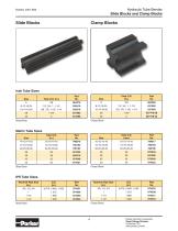
Hydraulic Tube Bender Slide Blocks and Clamp Blocks Slide Blocks Clamp Blocks Clamp Block Slide Block Slide Block IPS Tube Sizes Nominal Pipe Size (in.) 3/8, 1/2, 3/4 1 1-1/4 1-1/2 Clamp Block Slide Block Parker Hannifin Corporation Tube Fittings Division Columbus, OH www.parker.com/tfd
Open the catalog to page 6
Hydraulic Tube Bender Medium to Heavy Wall Tube Bending The bender is shipped completely assembled except for attaching a pump, hose, and installing selected bender dies. Step 1: Mounting Tube Bender Position bender centered across the end of bender table and bolt securely in place. The Parker bender table has pre-drilled holes for bender attachment. Step 2: Connect Pump to Bender Connect the hose assembly (part no. 910004) to the pump (3/8" NPT end) and then connect hose to the bender. Be careful not to twist the hose when tightening. Use a pipe sealant on the pipe threads. The makeup for the...
Open the catalog to page 7
Hydraulic Tube Bender Medium to Heavy Wall Tube Bending Step 5: Select Slide and Clamp Block Grooves Select the proper groove of the slide block and clamp block for the outside diameter of tube (sizes are marked on end of each block). Lubricate the slide block to facilitate its sliding. Place the clamp block in its vise. Do not lubricate the clamp block. It’s held in place magnetically. Step 6: Rapid Positioning Both the clamp and slide block vise screws feature rapid positioning, with a quick acting cam lock mechanism. To use, pull the respective cam lock mechanism to disengage, push the screw...
Open the catalog to page 8
Hydraulic Tube Bender Medium to Heavy Wall Tube Bending Step 9: Using the Tie Bar (when required) If the tube is over 1" O.D. (25mm or 1/2 IPS), or heavy wall, or if mandrel bending, the tie bar must be used to prevent tube slippage and the clamp arm from flexing. Step 11: Bending the Tube To bend the tube, start the pump and close the valve. CAUTION — Should it become apparent that the bend is too long for the slide block, stop the bender and loosen the slide block vise. Return the slide block to its original position. Retighten the vise screw and complete the bend. Step 10: Setting Bend Angle...
Open the catalog to page 9
Hydraulic Tube Bender Thin Wall Tube Bending with Mandrel Equipment When to Mandrel Bend For short radii bends and thin-wall tubing, mandrel equipment is necessary to prevent wrinkling, collapsing, or kinking of the tube. The mandrel supports the tube wall on the inside and maintains a full crosssection in a smooth bend. This is important and should be included as an indispensable part of bending equipment. The rule that is generally followed to determine whether or not a mandrel is necessary is as follows: When the wall thickness of the tube to be bent is 7% or more of the tube O.D., a mandrel...
Open the catalog to page 10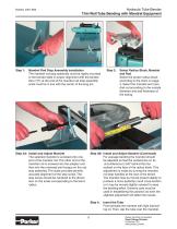
Hydraulic Tube Bender Thin Wall Tube Bending with Mandrel Equipment Step 1: Mandrel Rod Stop Assembly Installation The mandrel rod stop assembly must be rigidly mounted to the bender table in proper alignment with the bender. Zero (“0”) at the end of the mandrel rod stop assembly scale must be in line with the center of the king pin. Step 3A: Install and Adjust Mandrel The selected mandrel is screwed onto one end of the mandrel rod. The other end of the mandrel rod is screwed into the adapter and then into the universal joint tongue on the rod stop assembly. The scale provided permits accurate...
Open the catalog to page 11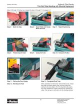
Hydraulic Tube Bender Thin Wall Tube Bending with Mandrel Equipment Steps 5 through 12 below are a repeat of steps 4 through 11 on pages 5-7. Step 5: Mark the Tube Step 6: Select Slide and Clamp Block Grooves Step 7: Rapid Positioning Step 8: Positioning the Tube Step 9: Clamp the Tube Step 11: Setting the Bend Angle Step 13: Completed Bent Tube Step 12: Bending the Tube After completion of the bend, remove the tie bar, retract the slide and clamp block vises, and by pulling the tubing to the left, slide it off of the mandrel rod assembly. Then release the system pressure by opening the valve....
Open the catalog to page 12All Parker Tube Fittings Division catalogs and technical brochures
 JIS Fittings
8 Pages
 Pipe Swivels
8 Pages
 Pipe Fittings and Port Adapters
26 Pages
 ParKlamp Inch Tube Clamps
16 Pages
 O-Rings and Seals
10 Pages
 Metric Tube
6 Pages
 Metric Clamps
12 Pages
 Komatsu® Style Adapters
6 Pages
 K4 BSP Adapters
10 Pages
 JIS Fittings
8 Pages




Archived catalogs
 Conversion Adapters
6 Pages
 Couplings & Equipment
20 Pages
 Catalog 0600P-9/USA
4 Pages
 Quick Coupling Products
214 Pages
 USA Industrial Hose Products Catalog
258 Pages
 Quick Coupling Products
209 Pages
 Prestolok Plus Fittings Catalog
8 Pages
 Global Connect Fittings Catalog
12 Pages
 X-treme Silicone Hose
36 Pages


- Parker hydraulic fitting
- Parker screw-in fitting
- Pneumatic fitting
- Parker metal fitting
- Metal sawing line
- Quick coupling
- Parker stainless steel fitting
- Bender
- Nickel-plated brass fitting
- Parker elbow fitting
- Threaded fitting
- Plastic fitting
- Parker male fitting
- Parker T-shaped fitting
- Machine vise
- Push-in fitting
- Tube bending cell
- Parker poppet fitting