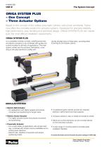
Overview: The document provides a comprehensive overview of the ORIGA SYSTEM PLUS (OSP-E) modular
electric actuators by Parker Hannifin Corporation. It highlights the system's modularity, allowing for the combination of pneumatic and electric actuators with guides and control modules for various applications. The system is designed for reliability, high performance, and easy handling.
Main Components:- Electric Belt Actuators: Suitable for applications requiring high speeds and precise positioning over long distances.
- Electric Screw Actuators: Designed for higher power applications with precise movement and positioning.
- Pneumatic Actuators: Ideal for fast, repetitive movements with simple control possibilities.
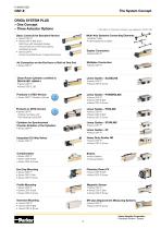
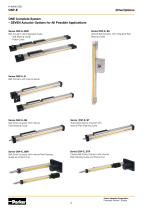
Actuator Options: The document details seven actuator options, including belt actuators with integrated guides, vertical belt actuators, and screw actuators with internal plain bearing guides. Each option is tailored for specific applications, offering various features such as integrated ball bearing guides, roller guides, and piston rods.
Specifications: Detailed technical specifications are provided for each actuator type, including effective action force, maximum velocity, temperature range, and available options like tandem versions and integrated planetary gearboxes.
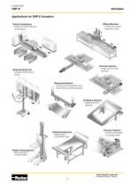
Applications: The OSP-E actuators are versatile and can be used in a wide range of applications, including material handling systems, automated filling machines, robotic installations, conveyor systems, and medical equipment. Specific examples include high-speed pick and place movements, accurate 3-axis positioning, and synchronized bi-parting movements.
Accessories and Mountings: The document lists various accessories and mounting options available for the actuators, such as magnetic sensors, motor mountings, and multi-axis connection systems. These components enhance the flexibility and adaptability of the actuators for different industrial applications.
Conclusion: The ORIGA SYSTEM PLUS offers a complete solution for actuator systems, combining modularity with high performance and reliability. It is suitable for a wide range of industrial applications, providing precise control and flexibility in installation.
OSP-E..BHD Series Overview: The document details the specifications and features of the OSP-E..BHD series of electric
linear actuators by Parker Hannifin Corporation, designed for high capacity and precision applications. These actuators are equipped with integrated guides and optional planetary gearboxes, making them suitable for heavy-duty applications.
Specifications: The OSP-E..BHD series includes various models (OSP-E20BHD, OSP-E25BHD, OSP-E32BHD, OSP-E50BHD) with different weight, inertia, and performance characteristics. The actuators can operate at speeds up to 10 m/s and support high load capacities. They are constructed with materials like anodized aluminum and steel-corded polyurethane belts.
Features: Key features include integrated ball bearing or roller guides, diverse mounting options, and compatibility with multi-axis systems. The actuators offer high force output, speed, and load capacity, with easy installation and low maintenance requirements.
Options and Accessories: The actuators can be customized with options like tandem versions for higher moments, bi-parting versions for synchronized movements, and integrated planetary gearboxes for compact installations. Accessories include motor mountings, end cap mountings, and magnetic sensors for position sensing.
Installation and Maintenance: Installation instructions emphasize securing at least one end cap to prevent axial sliding. Maintenance is recommended after 12 months or 3000 km of operation. The document also provides guidelines for actuator sizing and load calculations.
Performance and Load Calculations: Detailed tables provide information on maximum permissible loads, torque, and speed for different actuator models. The document outlines steps for calculating static and dynamic forces and moments, ensuring that combined loads do not exceed specified limits.
Conclusion: The OSP-E..BHD series offers robust and versatile solutions for various industrial applications, with a focus on precision, adaptability, and performance. The document provides comprehensive technical data and guidelines for selecting and using these actuators effectively.
Installation Instructions: Use the threaded holes in the end cap for mounting the actuator. Ensure at least one end cap is secured to prevent axial sliding when profile mountings are used. Refer to the graph on page 22 to determine if profile mountings are necessary based on the maximum allowable unsupported length.
Maintenance: Inspect the actuator after 12 months or 3000 km of operation, depending on conditions. Follow the operating instructions provided with the actuator.
Standard Versions: Includes Belt Actuator with Integrated Roller Guide, Drive Shaft with Clamp or Plain Shaft, choice of Motor Mounting Side, and Dovetail Profile for accessory mounting.
Options: Tandem Version for higher moments, Bi-parting Version for synchronized movements, Integrated Planetary Gearbox, and special drive shaft versions upon request.
First Service Start-up: Do not exceed the maximum values specified in the technical data sheet. Ensure compliance with the EC Machine Directive 2006/42/EG before using the actuator as a machine.
Weight and Inertia: Detailed weight and inertia values are provided for different series and configurations, including tandem and bi-parting options.
Characteristics: The actuator features a linear drive with a toothed belt and integrated roller guide, suitable for installation in any position. It operates within an ambient temperature range of -30°C to +80°C and has a protection class of IP 54.
Maximum Permissible Torque on Drive Shaft: Torque values are provided for different speeds and strokes for series OSP-E25BHD, OSP-E32BHD, and OSP-E50BHD.
Sizing of Actuator: Steps include determining lever arm length, calculating load and static/dynamic forces, selecting permissible loads, and checking maximum torque and action force requirements.
Maximum Permissible Loads: Maximum applied loads and moments are specified for each series, with a performance overview detailing speed, action force, and other key parameters.
Stroke Length: Actuators are available in multiples of 1 mm up to 5700 mm. Additional safety clearance is required at both ends, especially when using an AC motor with a frequency converter.
Combined Loads: The total of the loads must not exceed a value of 1 under any circumstances, ensuring the maximum permissible loads are not exceeded.
Accessories: Various accessories are available, including motor mountings, magnetic sensors, and profile mountings, with specific order instructions provided.
Specifications and Features: The document outlines the specifications for the OSP-E series of vertical belt actuators with integrated ball bearing guides, available in sizes 20 and 25. Key features include a vertical belt actuator with a choice of motor mounting sides, options for tandem versions for higher moments, and various drive shaft configurations. The actuators are made from extruded anodized aluminum with steel-corded polyurethane belts and hardened steel guide rails.
Performance and Maintenance: The maximum speed for the OSP-E20BV is 3.0 m/s and for the OSP-E25BV is 5.0 m/s, with a maximum acceleration/deceleration of 20 m/s². The actuators have a repeatability of +/- 0.05 mm/m and a maximum standard stroke length of 1,000 mm for the OSP-E20BV and 1,500 mm for the OSP-E25BV. Maintenance is recommended after 12 months or 3000 km of operation.
Weight and Inertia: The document provides detailed tables on the weight, moving mass, and inertia for different series and configurations, including tandem options. For example, the OSP-E20BV has a total weight of 3.4 kg and a moving mass of 1.9 kg.
Installation and Sizing: Installation instructions emphasize the importance of correct center of gravity distance and proper mounting of external masses. The document provides a step-by-step guide for sizing the actuator, including calculations for static and dynamic forces and moments, and checking permissible loads and torques.
Options and Accessories: Various options and accessories are available, including magnetic sensors for contactless position sensing, motor mounting kits, and different drive shaft configurations. The document also details the order instructions for specifying the actuator type, size, and additional features.
Safety and Compliance: Users must ensure compliance with the EC Machine Directive 2006/42/EG before using the actuator as a machine. The document stresses the importance of not exceeding the maximum values specified in the technical data sheet.
OSP-E Series Overview: The document provides detailed technical specifications and operational guidelines for Parker Hannifin's OSP-E series belt actuators with internal plain bearing guides. It includes information on standard and optional versions, characteristics, sizing, performance, and ordering instructions.
Specifications: The OSP-E series includes models OSP-E25B, OSP-E32B, and OSP-E50B, each with varying weight, inertia, and maximum permissible loads. The actuators are designed with a slotted profile made of extruded anodized aluminum, steel-corded polyurethane belts, and low friction plastic guide bearings. The encapsulation class is IP 54, suitable for various industrial applications.
Procedures: The document outlines the first service start-up requirements, emphasizing adherence to the EC Machine Directive 2006/42/EG. It provides a step-by-step guide for actuator sizing, including calculating required acceleration, torque, and ensuring maximum values are not exceeded.
Performance and Load Capacities: The maximum speed varies from 2 to 5 m/s depending on the model, with a repeatability of ±0.05 mm/m. The document details the maximum permissible torque on the drive shaft and provides equations for calculating combined loads.
Options and Accessories: Options include tandem and bi-parting versions for synchronized movements, various motor and gear mounting kits, and external guides. The document also lists available accessories such as magnetic sensors and motor mountings.
Ordering Instructions: Detailed instructions are provided for ordering different actuator sizes, types, and configurations, including carriage options, drive shaft positions, and additional accessories.
Graphical Data: The document includes graphs for distance/time and required torque/mass, aiding in the selection of appropriate actuator configurations based on application requirements.
OSP-E Series Ball Screw Actuators: The document provides detailed technical specifications and options for the OSP-E series ball screw actuators with internal plain bearing guides, certified for clean room use according to DIN EN ISO 14644-1. It includes various mounting options, maintenance guidelines, and installation instructions.
Specifications: The OSP-E series includes sizes 25, 32, and 50, with different pitches for the ball screw spindle. The actuators are designed for high precision and can be mounted in any position. They are made from materials like hardened steel and anodized aluminum, with a protection class of IP 54.
Options: Available options include tandem versions for higher moment support, magnet sensors for contactless position sensing, and various mounting configurations such as clevis, end cap, and profile mounting.
Maintenance: The actuators are long-term lubricated, but Parker recommends checking and lubricating them after 12 months or 3000 km of travel. Adherence to the EC Machine Directive 2006/42/EG is required before use.
Installation Instructions: The document provides detailed instructions for mounting the actuators, including the use of threaded holes and profile mountings. It emphasizes the importance of securing end caps to prevent axial sliding and using compensation when moving externally guided loads.
Performance and Sizing: The document includes graphs and tables for sizing the actuators, showing recommended maximum acceleration, required torque, and maximum permissible loads. It also provides equations for calculating combined loads and emphasizes not exceeding maximum permissible loads.
Order Instructions: Detailed instructions are provided for ordering the actuators, including options for pitch, mounting kits, drive shafts, and additional accessories like magnetic sensors and profile mountings.
Additional Features: The document also describes the OSP-E..ST trapezoidal screw actuator, highlighting its advantages such as accurate path control, high force output, and low maintenance requirements.
OSP-E Series Trapezoidal and Ball Screw Actuators: The document provides detailed technical specifications and guidelines for the OSP-E series of actuators by Parker Hannifin Corporation, Pneumatic Division - Europe. It covers both trapezoidal screw actuators and ball screw actuators with internal plain bearing guides.
Specifications: The OSP-E..ST series includes trapezoidal screw actuators available in sizes 25, 32, and 50, with pitches of 4 mm for sizes 25 and 32, and 6 mm for size 50. The OSP-E..SBR series includes ball screw actuators with pitches of 5 mm, 10 mm, and 25 mm depending on the size.
Features: Both actuator types feature a dovetail profile for mounting accessories, integrated magnet sets for contactless position sensing, and options for motor mountings and magnetic sensors. The ball screw actuators offer high output force, excellent running characteristics, and high levels of repeatability.
Installation and Maintenance: Installation instructions emphasize the use of threaded holes and profile mountings to secure the actuators. Maintenance involves checking and lubricating moving parts after 12 months or 300 km of travel. The document advises against using the mechanical end position as a stop and recommends safety clearances.
Performance and Load Capacities: The document provides detailed tables and graphs for maximum permissible loads, moments, and unsupported lengths. It specifies maximum speeds, linear motion per revolution, and effective action forces for each actuator size.
Options and Accessories: Various options include displacement measuring systems, keyways, and different mounting kits for motors and gears. Accessories such as motor mountings, magnetic sensors, and profile mountings are available for customization.
Order Instructions: Detailed instructions are provided for ordering actuators, specifying size, type of drive, carriage, pitch, and additional options like magnetic sensors and profile mountings.
Specifications and Safety Instructions: The document outlines the specifications for mechanical end stops, emphasizing the need for additional safety clearance at both ends equivalent to the linear movement of one revolution of the drive shaft, with a minimum of 25 mm. The order stroke is calculated as the required travel plus twice the safety distance. It is noted that AC motors with frequency converters typically require larger safety clearances than servo systems.
Order Instructions: The document provides detailed order instructions for the OSP-E series, including size options (25, 32, 50), type of drive, pitch, order stroke, and mounting kits for motors and gears. It specifies the drive shaft options and gear mounting configurations, with references to additional pages for motor and gear mounting dimensions.
Magnetic Sensors and Profile Mounting: Options for magnetic sensors and profile mounting are listed, with references to further pages for detailed information. The document also includes instructions for ordering accessories separately.
Linear Guides Overview: The document describes various linear guides available in the Origa System Plus (OSP), including SLIDELINE, POWERSLIDE, PROLINE, and HD-Guide, each designed for different load capacities and precision requirements. It highlights the advantages of these guides, such as high load capacity, precision, smooth operation, and retrofit capabilities.
Technical Data and Dimensions: Technical data tables provide maximum permissible values for loads, forces, and moments for different series and sizes. The document includes detailed dimension tables for each series, specifying measurements for various components.
Performance and Lubrication: Performance calculations involve determining the load factor and calculating service life in kilometers. The document emphasizes the importance of maintaining lubrication for maximum system life, recommending high-quality lithium-based greases and regular inspections based on environmental conditions.
Conclusion: The document serves as a comprehensive guide for ordering and configuring linear guides and actuators in the OSP-E series, providing detailed specifications, order instructions, and technical data to ensure optimal performance and safety.
OSP-E Series Pneumatic Actuators: This document provides technical specifications and guidelines for the OSP-E series of pneumatic actuators and related components by Parker Hannifin Corporation. It includes details on guide positions, load capacities, technical data for various series, and information on planetary and angular gears.
Specifications:- Guide Positions: Options include standard, opposite the drive shaft, and same side as the drive shaft. Proper guide mounting is necessary to prevent deflection and vibration.
- Load Capacities: Maximum permissible loads and moments are specified for different series (HD25, HD32, HD50) with detailed load case scenarios.
- Technical Data: Includes maximum moments, load capacities, and mass for actuators with guides. The document specifies the maximum velocity and features like integrated wipers and polished guide rails.
Procedures:- Guide Mounting: Essential for preventing excessive deflection. The document provides diagrams for maximum unsupported lengths relative to loading.
- Installation: Heavy-duty guides must be fitted to a level surface, with T-nuts spaced no more than 100 mm apart.
Norms and Standards:- Efficiency and Performance: The document outlines efficiency ratings, operating noise levels, and protection classes for various components.
- Operating Conditions: Specifies operating temperature ranges and lifetime expectations for components.
Recommendations:- Use of Gears: Planetary and angular gears are recommended for reducing motor torque requirements and achieving good inertia mismatch.
- Controller Selection: Microstepping controllers are suitable for precise movements, while servo controllers are recommended for dynamic motion profiles.
Key Data Tables:- Load and Moment Capacities: Detailed tables provide maximum permissible values for different series and configurations.
- Gear Specifications: Includes data on nominal torque, maximum acceleration torque, and emergency stop torque for planetary and angular gears.
- Controller Specifications: Technical data for microstepping and servo controllers, including output voltage, current, and digital inputs/outputs.
EasyDrive Stepper and Servo Motors: This document provides technical specifications and details for Parker Hannifin Corporation's EasyDrive Stepper and Servo Motors, specifically the SY563T, SY873T, SMB60, and SMB82 series. It includes torque curves, dimension tables, and package configurations for various motor types.
Specifications:- Stepper Motors (SY563T, SY873T): Nominal speed is 900 min-1, with nominal torque ranging from 0.8 to 2.5 Nm. Critical speed is 1,800 min-1, and torque at critical speed ranges from 0.5 to 1.2 Nm. Current per phase is between 6.5 to 8.4 A, with inductivity per phase from 1.2 to 1.7 mH. Inertia and weight vary between models.
- Servo Motors (SMB60, SMB82): Standstill torque ranges from 1.4 to 3.0 Nm, with nominal speed up to 3,000 min-1. Peak torque is between 3.0 to 4.5 Nm. The motors have a holding brake with a torque of 2.2 to 5.0 Nm and a supply voltage of 24 VDC.
Torque Curves:- SY563T and SY873T: The torque curves illustrate the characteristic and secure torque profiles across various speeds, highlighting the performance limits of each motor.
- SMB60 and SMB82: The torque curves show nominal and peak torque capabilities, indicating the maximum performance thresholds.
Dimensions: Detailed dimension tables are provided for each motor type, specifying measurements such as diameter, length, and mounting configurations.
Packages and Accessories:- EasyDrive packages include controllers, motors, and cables. Specific configurations are available for different motor series and applications.
- Accessories such as power supplies, I/O connection cables, and communication cables are listed with order numbers for easy reference.
Mounting and Coupling: The document details various motor mounting options, including coupling housings and motor flanges, to facilitate integration with actuators and other components.
OSP-E Series Actuators: This document provides technical specifications and mounting instructions for the OSP-E series actuators by Parker Hannifin Corporation, Pneumatic Division - Europe. It includes details on various actuator types, mounting dimensions, and order instructions.
Specifications:- Actuator Types: OSP-E..B (Belt Actuator with Internal Plain Bearing Guide), OSP-E..SB, ..ST (Screw Actuator with Internal Plain Bearing Guide), OSP-E..SBR, ..STR (Screw Actuator with Internal Plain Bearing Guide and Piston Rod).
- Sizes: 25, 32, 50.
- Materials: Anodized Aluminium and Galvanised Steel.
Mounting Dimensions:- Freely Selectable Mounting Dimensions: Allows for flexible motor connections.
- Counterbore and Thread Versions: Available in "S" (Counterbore) and "M" (Thread) versions.
- Dimension Tables: Provided for both belt and screw drive versions, detailing minimum and maximum dimensions for various sizes and angles.
Order Instructions:- Details on ordering specific configurations, including drive shaft options (plain or with keyway).
- Order numbers provided for different configurations and sizes.
Mounting Instructions:- End Cap Mounting: Instructions for sizes 20, 25, 32, 50, with specific order numbers for each type.
- Profile Mounting: Details on mounting profiles for sizes 20, 25, 32, 50, including weight specifications.
- Adaptor Profile: Universal attachment for additional items, with dimensions and order instructions.
Key Considerations:- Ensure compatibility of motor flange dimensions with actuator specifications.
- Consider material options based on environmental requirements (e.g., stainless steel versions available on request).
- Follow specific order instructions to ensure correct configuration and delivery.
OSP-E Series Mounting Options: The document provides detailed technical specifications and instructions for various mounting options and components related to the OSP-E series of actuators by Parker Hannifin Corporation, Pneumatic Division - Europe. It includes information on trunnion and pivot mountings, clevis mountings, inversion mountings, piston rod components, and magnetic field sensors.
Trunnion and Pivot Mountings: These mountings are adjustable and supplied in pairs, suitable for sizes 25, 32, and 50. The document lists dimensions and order instructions for each type, with specific order numbers for different series and sizes.
Clevis Mountings: Designed for low backlash and compensation in various directions, these mountings are available in standard and stainless steel versions. They help avoid mechanical strain by allowing freedom of movement in multiple directions.
Inversion Mountings: Recommended for dirty environments or space constraints, these mountings transfer driving force to the opposite side of the cylinder. They maintain the same mounting hole size and position as standard cylinders.
Piston Rod Components: The document details specifications for piston rod eyes and clevises according to ISO standards, including dimensions, weights, and order numbers. It also covers compensating couplings for angular and radial compensation.
Profile and End Cap Mountings: Various types of profile and end cap mountings are described, with dimensions and order instructions provided. These mountings are designed for different positions and are available in reinforced versions.
Magnetic Field Sensors: The document introduces a new generation of T-slot sensors with easy mounting and accurate switching points. It includes technical data, electrical characteristics, and installation instructions for different sensor types, emphasizing protective measures for electrical service life.








 Moduflex Valve System
 Air Saver Module HASV08G
 Pneumatic Products Spare Parts
 Pneumatic Linear Drives OSP-L
 XLB Series Base Slides
 GDL Aluminum Roller Guides
 Industrial Shock Absorbers
 Rotary Actuators
 Dryer Products
 Pneumatic Products LOAD-TAMER™
 Pneumatic Product Catalog


 Automation Air Control Valves

