- Catalogs
- Parker Industrial Gas Filtration and Generation Di
- HY17-8562-UK_M250LS
HY17-8562-UK_M250LS
1 /24Pages
HY17-8562-UK_M250LS
1 /24Pages
Catalog excerpts
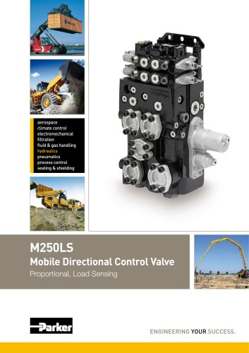
Mobile Directional Control Valve Proportional, Load Sensing ENGINEERING YOUR SUCCESS.
Open the catalog to page 1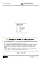
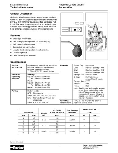
Mobile Directional Control Valve Conversion factors A WARNING - USER RESPONSIBILITY FAILURE OR IMPROPER SELECTION OR IMPROPER USE OF THE PRODUCTS DESCRIBED HEREIN OR RELATED ITEMS CAN CAUSE DEATH, PERSONAL INJURY AND PROPERTY DAMAGE. This document and other information from Parker-Hannifin Corporation, its subsidiaries and authorized distributors provide product or system options for further investigation by users having technical expertise. The user, through its own analysis and testing, is solely responsible for making the final selection of the system and components and assuring that all performance,...
Open the catalog to page 2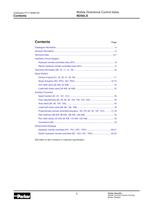
Mobile Directional Control Valve Contents Page Hydraulic Circuit Diagram Spool Section Auxiliary Functions Dimensional Drawings [00] refers to item numbers in customer specification. Parker Hannifin Mobile Controls Division Europe Boràs, Sweden
Open the catalog to page 3
Catalogue Information Mobile Directional Control Valve Parker is the world's leading supplier of motion control components and system solutions serving the mobile, industrial Parker is your single source for any hydraulic valve requirement. We provide a wide selection of open-centre and load-sense directional control valves for construction, off-highway, or on-highway applications. Many of our open-centre valves can be adapted and used as constant-pressure unloaded valves. Each of these technologies offers unique features for improved machine perform- ance over traditional, open-centre control...
Open the catalog to page 4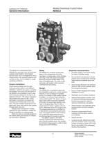
General Information Mobile Directional Control Valve intended for machines such as small and midsize wheel loaders, mine loaders, fork-lift trucks, etc. It is designed for use in closed-centre (LS) hydraulic systems with variable pumps, and is suitable for tough operating conditions. Simple installation Good machine design and the right hydraulic system gives a cost-effective installation, which in turn gives a competi- tive product. The pump and work ports in that hosing and piping can be kept to an absolute minimum. The valve is equipped with double work ports at 180°, which eliminates T-connectors...
Open the catalog to page 5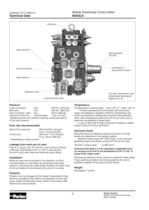
Technical Data Mobile Directional Control Valve Pump connection Spool actuators float position function Sequence valve Load-hold check valve Tank connection, static max. 20 bar (290 psi) Pressure in drain line recommended 1 bar (14.5 psi) *Stated pressures are maximum absolute shock pressures at Flow rate (recommended) Return from work port "Depending on choice of spool. Leakage from work port to tank 30 mm2/s (cSt), when fitted with load-hold check valves. While the valve can be mounted in any direction, it is best mounted upright (i.e. with lifting eye upwards) to give good access for servicing...
Open the catalog to page 6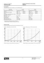
Technical Data Mobile Directional Control Valve Pump, tank and work-port connections are of the SAE flange type. * High pressure (400 bar) according to ISO 6162. ** Standard pressure (330 bar) according to ISO 6162. Pressure drop Pressure drop measured with fully open spool intended for max. flow. Ap (bar) Pressure drop - work port to tank Ap (bar) Pressure drop - P1/P2 to work port A/B Pressure drop from work port A/B to tank connection T. Pressure drop from pump connection P1/P2 to work port A/B. Parker Hannifin Mobile Controls Division Europe Borás, Sweden
Open the catalog to page 7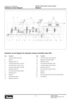
Hydraulic Circuit Diagram Mobile Directional Control Valve Hydraulic circuit diagram for hydraulic 1 Counter pressure valve [10] 4 Load-hold check valve, A1 [34 A] 5 Port relief valve, A1 [32 A, 33 A] 6 Load-hold check valve, B1 [34 B] 8 Port relief valve, B1 [32 B, 33 B] 11 Float position device 13 Load-hold check valve, B2 [54 B] 14 Sequence spool float position 16 Port relief valve, B2 [52 B, 53 B] 17 Load-hold check valve, A2 [54 A] 19 Port relief valve, A2 [52 A, 53 A] 22 Port relief valves [72 A/B, 73 A/B, 92 A/B, 93 A/B] Parker Hannifin Mobile Controls Division Europe Borás, Sweden
Open the catalog to page 8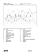
Hydraulic Circuit Diagram Mobile Directional Control Valve Hydraulic circuit diagram for electro 1 Counter pressure valve [16] 4 Load-hold check valve, A1 [34 A] 5 Port relief valve, A1 [32 A, 33 A] 6 Load-hold check valve, B1 [34 B] 8 Port relief valve, B1 [32 B, 33 B] 11 Float position device ic remote controlled valve (EC) 13 Load-hold check valve, B2 [54 B] 14 Sequence spool float position 16 Port relief valve, B2 [52 B, 53 B] 17 Load-hold check valve, A2 [54 A] 19 Port relief valve, A2 [52 A, 53 A] 22 Port relief valves [72 A/B, 73 A/B, 92 A/B, 93 A/B] Parker Hannifin Mobile Controls Division...
Open the catalog to page 9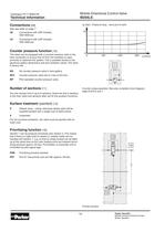
Technical Information Mobile Directional Control Valve Also see table on page 7. U6 Connections with UNF threads, U3 Connections with UNF threads, Counter pressure function [io] The valve can be equipped with a counter pressure valve in the tank connection to ensure that oil from the cylinders is used primarily to replenish the system. This is possible thanks to the generous gallery dimensions and anti-cavitation valves. The valve MX No counter pressure valve in tank gallery. MF4 Counter pressure valve set to 4 bar at 20 l/min. MP Pilot operated counter pressure valve. You can choose from 2 up...
Open the catalog to page 10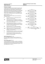
Spool Section Mobile Directional Control Valve The spool is the most important link between the actions of the machine operator and the movement of the controlled function. Parker therefore goes to great lengths to optimize spools for different flows, load conditions and functions. This ongoing devel- opment work results in the continual introduction of new spools. For this reason, it is not practical to list in this catalogue the different spools available at any one time. For assistance in the choice of spool, we therefore ask you to contact Parker directly. Parker spools are divided into different...
Open the catalog to page 11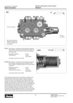
Spool Actuators Mobile Directional Control Valve PC-PC Both section 1 and section 2 have hydraulic, proportion- ally controlled, spring-centred spool actuators. Best con- trolled by a PCL4 remote control valve (see catalogue Breakaway pressure:* Final pressure:* PC-FPC Both section 1 and section 2 have hydraulic, proportion- ally controlled, spring-centred spool actuators with a fourth position for shifting the spool into the float position Breakaway pressure:* Final pressure:* Pressure for float position: The breakaway pressure refers to the pressure needed for the directional valve to open...
Open the catalog to page 12All Parker Industrial Gas Filtration and Generation Di catalogs and technical brochures
 HY17-8542-UK_QDS6
8 Pages
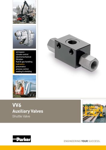 HY17-8602-UK_VV6
8 Pages
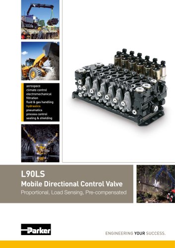 HY17-8504-UK_L90
44 Pages
 HY17-8557-UK_K170
24 Pages
 Y14
Y142 Pages
 HY17-8702-UK_PLC
12 Pages
 7-EN%205150-B%20-%20CAR.
15 Pages
 Cover
Cover2 Pages
 HY14-3000FrtCvr
2 Pages
 HY17-8534-UK_F130
32 Pages
 20Lo-Torq
2 Pages

Archived catalogs
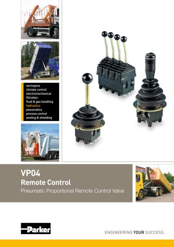 HY17-8356-UK_VP04
12 Pages
 Natural Gas Solutions
12 Pages


- Chiller
- Parker cartridge filter
- Filter cartridge
- Liquid recirculation chiller
- Industrial use filter
- Pressure separator filter
- Stainless steel pre-filter
- Industrial filter cartridge
- Fine filter cartridge
- Filtration unit
- Water recirculation chiller
- Automatic test kit
- Industrial cooling system
- Water filter cartridge
- Parker compressed air dryer
- Compact recirculation chiller
- Plastic filter cartridge
- General purpose filter cartridge
- Nitrogen generator
- Parker gas filter