- Catalogs
- Parker Industrial Gas Filtration and Generation Di
- HY17-8557-UK_K170
HY17-8557-UK_K170
1 /24Pages

HY17-8557-UK_K170
1 /24Pages
Catalog excerpts
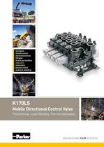
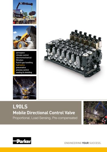
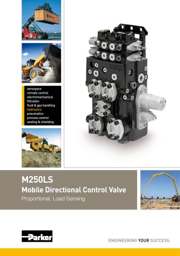
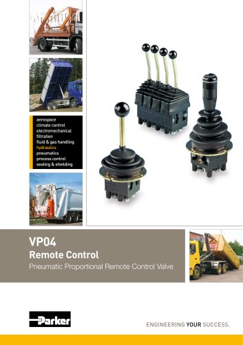
climate control process control sealing & shielding Mobile Directional Control Valve Proportional, Load Sensing, Pre-compensated ENGINEERING YOUR SUCCESS.
Open the catalog to page 1
Catalogue Information Mobile Directional Control Valve Catalogue layout This catalogue has been designed to give a brief overview of K170LS valves, and to make it easy for you to study and choose from the different options available, so that we may customize your valve in accordance with your wishes. In addition to general information and basic technical data, the catalogue therefore contains descriptions of the options available for various so-called "function areas" of the valve. Each function area is given as a subheading, followed by a brief description. When options are available for a function...
Open the catalog to page 2
Mobile Directional Control Valve Contents Page [00] refers to item numbers in the customer specification. Parker Hannifin Mobile Controls Division Europe Borás, Sweden
Open the catalog to page 3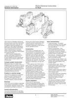
General Information Mobile Directional Control Valve directional control valve, which can also be adapted to give force-feedback. It is designed for many different applications, both mobile and industrial, and is widely used in machines such as front-end loaders, backhoe loaders, excavators, cranes, forestry equipment, metal presses With its function-adapted spool sections, wide range of additional func- tions and standard accessories, the K170LS enables the user to optimise the machine and its hydraulic system in the following ways: Compact system construction While the K170LS can contain many...
Open the catalog to page 4
General Information Mobile Directional Control Valve K170LS with built-in hydraulic, electro-hydraulic, or combined manual and electro-hydraulic spool actuator. In this example, the valve is not equipped with a copying function for the load signal The K170LS valve connected to a L90LS valve. The L90LS valve is used for functions which requires less flow. This gives price ad- vantages as well as operational advantages. The valve in this ex- ample fitted with an internal pilot pressure supply and individual pressure compensator, feed reduction and pressure relief valves. Parker Hannifin Mobile...
Open the catalog to page 5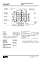
Technical Data Mobile Directional Control Valve Load pressure Gauge port, Pump pressure Copied load Pilot pressure Tank connection Tank connection Pump connection from parallel valve [31] counter pressure hydraulic remote Separate tank pilot circuit, Pump inlet Service ports Return line pressure, static max 20 bar (290 psi) 1) Pressures given are maximum absolute relief pressures 2) Pressure drop pump to valve max 3 bar (44 psi) Internal pilot pressure Standard setting Optional setting Feed reducer Adjustment range Counter pressure valve Fixed setting Pilot operated, signal pressure Pressure...
Open the catalog to page 6
Mobile Directional Control Valve Filtration must be arranged so that Target Contamination Class 20/18/14 according to ISO 4406 is not exceeded. For the pilot circuit, Target Contamination Class 18/16/13 according to ISO Hydraulic fluids Best performance is obtained using mineral-base oil of high quality and cleanness in the hydraulic system. Hydraulic fluids of type HLP (DIN 51524), oil for automatic gear- boxes Type A and engine oil type API CD can be used. Viscosity, working range 15-380 mm2/s** Technical information in this catalogue is applicable at an oil viscosity of 30 mm2/s and temperature...
Open the catalog to page 7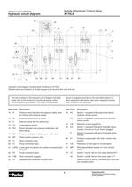
Hydraulic circuit diagram Mobile Directional Control Valve Hydraulic circuit diagram showing basic functions for K170LS Shaded zones are functions or function groups to be found further on in the text. The item numbers in the hydraulic circuit diagram and table below refer to the functions or function groups for which different options are available. The valve in the example above is equipped according to the description below. For other equipment alternatives, see under respective function [item number] in the catalogue. Item Code Description Item Code 12 R Pressure reducing valve with separate...
Open the catalog to page 8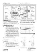
Inlet Section Mobile Directional Control Valve Pump connection Pressure relief Load signal copy spool Load pressure Gauge port pump pressu Tank connection Counter pressure valve. Tank connection pilot pressure Pilot strainer Pilot pressure supply connection Load pressure (copied) The inlet section is equipped with pump (P1) and tank connec- tions (T1, T2), a connection for the load signal to LS pumps (LS), a connection for pilot pressure supply for external use (PS), a gauge point for pump (PX) and load signal pressures (PL). In the basic variant, the pump connection P1 [26] and tank connection...
Open the catalog to page 9
Inlet Section Mobile Directional Control Valve Load signal system The load signal system consists of a number of shuttle valves, which compare the load signals from different spool sections and send the highest signal to the connection PL, or to a copying spool in the inlet section. The system permits a certain consumption in the load signal line to the pump, without the load signal level being affected. This enables simpler system design, with the possibility of installing logic systems in the LS circuit. Thanks to drainage in the pump LS regulator, the system gives better winter operating character-...
Open the catalog to page 10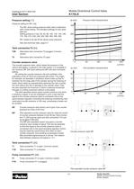
Inlet Section Mobile Directional Control Valve The PA1 direct acting pressure relief valve is delivered with a fixed setting. The standard settings (in bar) avail- PA1 needs to be set 20 bar above pump pressure. See also technical data, page 6-7. T2B Alternative tank connection T2 plugged. Common Pressure relief characteristics Alternative tank connection T2 open. Counter pressure valve The counter pressure valve, which raises the pressure in the valve's tank gallery, is placed in the inlet section. It is available in two versions: MF with fixed setting and MP with pilot-controlled By raising...
Open the catalog to page 11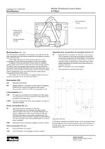
Mobile Directional Control Valve The end section is available in two variants, one with all connec- tions machined and one without machined connections for pump In the basic variant, the LS connection LSP [31], pump connection P2 [32] and tank connection T3 [34] are plugged. In addition to the two standard models, there is a special adapter plate (AP) which is used when the valve flanges against an L90LS valve. The adapter plate contains only the pilot tank connection and through channels which connect the pump, tank, pilot pump, pilot tank and LS channels of the K170LS and L90LS valves, respectively....
Open the catalog to page 12All Parker Industrial Gas Filtration and Generation Di catalogs and technical brochures
 HY17-8542-UK_QDS6
8 Pages
 HY17-8602-UK_VV6
8 Pages
 HY17-8504-UK_L90
44 Pages
 Y14
Y142 Pages
 HY17-8702-UK_PLC
12 Pages
 HY17-8562-UK_M250LS
24 Pages
 7-EN%205150-B%20-%20CAR.
15 Pages
 Cover
Cover2 Pages
 HY14-3000FrtCvr
2 Pages
 HY17-8534-UK_F130
32 Pages
 20Lo-Torq
2 Pages

Archived catalogs
 HY17-8356-UK_VP04
12 Pages
 Natural Gas Solutions
12 Pages


- Chiller
- Parker cartridge filter
- Filter cartridge
- Liquid recirculation chiller
- Pressure separator filter
- Industrial use filter
- Stainless steel pre-filter
- Industrial filter cartridge
- Fine filter cartridge
- Filtration unit
- Water recirculation chiller
- Automatic test kit
- Industrial cooling system
- Water filter cartridge
- Parker compressed air dryer
- Compact recirculation chiller
- Plastic filter cartridge
- General purpose filter cartridge
- Nitrogen generator
- Parker gas filter