- Catalogs
- Parker Industrial Gas Filtration and Generation Di
- HY17-8534-UK_F130
HY17-8534-UK_F130
1 /32Pages

HY17-8534-UK_F130
1 /32Pages
Catalog excerpts
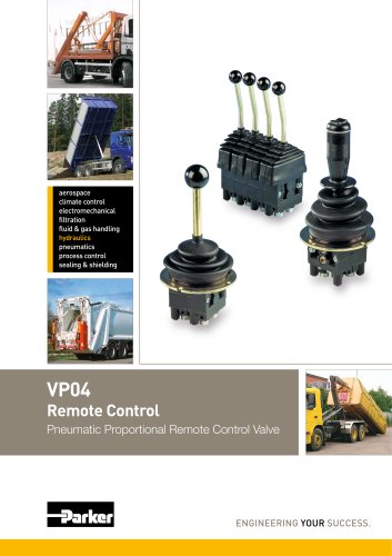
climate control process control sealing & shielding Mobile Directional Control Valve Proportional, Open or Closed Centre ENGINEERING YOUR SUCCESS.
Open the catalog to page 1
Catalogue Description Mobile Directional Control Valve Catalogue layout This catalogue is designed to give an overview of the F130CF directional valve and to show how it can be customised to meet your needs exactly. Apart from general information and basic technical data therefore, the catalogue contains descriptions of the variety of options available for the different function areas of the valve. After you have studied the options and made your selection, we will tailor your valve to meet your operating and control criteria. Each function area is given as a subheading, followed by a brief description....
Open the catalog to page 2
catalogue HY17-8534/UK Mobile Directional Control Valve Contents Page Hydraulic circuit diagram showing basic functions [00] refers to item numbers in customer specification. Parker Hannifin Mobile Controls Division Europe Borás, Sweden
Open the catalog to page 3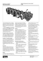
Valve Description Mobile Directional Control Valve The F130 directional valve is of modular construction. Designed for many different applications, it is used in cranes and other types of construction machine, forestry machines, refuse trucks, drill rigs, fork-lift The F130 is available in three different versions: the F130CF with an open centre for fixed pumps, the F130CP with a closed centre for variable displacement pumps and the F130LS with a closed centre, coupled with a load sensing signal, to the variable displacement pump. Compact system construction The valve is of modular construction...
Open the catalog to page 4
System Description Mobile Directional Control Valve Basic circuit diagram, CFO. For information about different hydraulic systems, see our system The F130 is designed with an open centre. The type diagrams on the right show the control characteristics The valve is also suitable for use in systems with variable pumps. q(l/min) Flow rate in service port In the F130CF with hand-operated spools, the speed is influen- ced by the size of the load, i.e. the heavier the lift load, the longer the lever stroke needed before the load starts to move, and the heavier the sink load, the quicker the lowering...
Open the catalog to page 5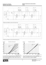
System Description Mobile Directional Control Valve Principle circuit diagram for valve with closed centre. Principle circuit diagram for valve with load sensing (LS). Flow rate in service port Flow rate in work port In the F130CP with hand-operated spools, all loads start moving In the F130LS equipped with PC and ECS closed spool- at the same point, regardless of the size and direction of the actuators, the spools are pressure compensated, with the result load. The size of the load does, however, affect the slope of the that the load's influence on speed is negligible. curve to some extent....
Open the catalog to page 6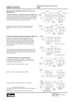
System Connection Mobile Directional Control Valve A. Series connection, multi-valve system, F130CF only The pump is connected to the first valve. Flow that is not directed to a consumer via the first valve continues to the next valve. The first valve therefore has priority and, in the event of full spool actuation in the first valve, no flow continues to the next valve. If an additional pump is connected to valve 2, then valve 2 receives the flow from pump 2 plus any residual flow from Inlet section End section Inlet section End section Spool section / \ Spool section B. Series connection, single-valve...
Open the catalog to page 7
Mobile Directional Control Valve F130 Catalogue HY17-8534/UK Technical Data Inlet section Pump connection P1 [27] Connections in mid-inlet section, M1, M3 [90] Service port B, section 2 Tank connection T2 [25] Spool actuator ECS3 [50] External pilot connection TP [40] Tank connection T3 [34] Service port A, section 1 Reduced pilot pressure PS End section [30] Spool end with hand lever attachment Tank connection T1 [33] Hand lever attachment Connection for hydraulic remote control, PC [50]. Actuation pump to service port A Pressure Connection Located G version UNF version P1, P2 inlet section...
Open the catalog to page 8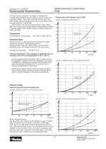
Environmental Characteristics Mobile Directional Control Valve The valve can be mounted in any direction. However, the mounting base should be flat and stable so that the valve is not subjected to strain. If the valve is mounted with the cap of the spool actuator facing downward, then cap A13 should be chosen The O-rings in the valve are mainly made of nitrile rubber, NBR. The O-rings in the joint face between the sections are made of hydrated nitrile rubber, HNBR, because HNBR tolerates heat Oil temperature, working range Hydraulic fluids Best performance is obtained using mineral-base oil of...
Open the catalog to page 9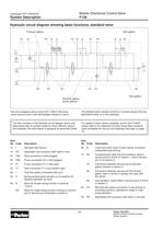
System Description Mobile Directional Control Valve Hydraulic circuit diagram showing basic functions, standard valve Pressure gallery Tank gallery Free-flow gallery (pump gallery) The circuit diagram above shows the F130CF with three The shaded areas indicate functions or function groups that are spool sections and a mid-inlet between sections 2 and 3. described further on in the catalogue. The item numbers in the hydraulic circuit diagram above and For details of other options available, and for the F130CP, table below refer to function areas for which different options please refer to the...
Open the catalog to page 10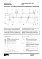
System Description Mobile Directional Control Valve Hydraulic circuit diagram showing basic functions (model with integral spool actuators) The circuit diagram above shows the F130 with three electro- hydraulically controlled spool sections and an integral pilot-oil supply. The shaded areas indicate functions or function groups that are described further on in the catalogue. The item numbers in the hydraulic circuit diagram above and table below refer to function areas for which different options are available. The valve above is equipped as described below. For details of other options available,...
Open the catalog to page 11
Inlet Sections Mobile Directional Control Valve Pump connection Main pressure relief valve [16] Standard inlet section The inlet section is available in two basic versions: the conventional version and aversion with pump unloading. The conventional inlet section has two pump connections, P1 and P2, and a tank connection, T2.The direct-acting main pressure relief valve is also located in the inlet section. The F130 with closed centre (F130CP, F130LS) is created by combining inlet section I with L or CUI at item [26]. The difference between the F130CP and the F130CF is that the free-flow gallery...
Open the catalog to page 12All Parker Industrial Gas Filtration and Generation Di catalogs and technical brochures
 HY17-8542-UK_QDS6
8 Pages
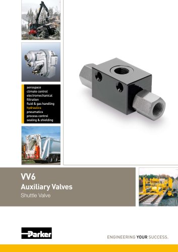 HY17-8602-UK_VV6
8 Pages
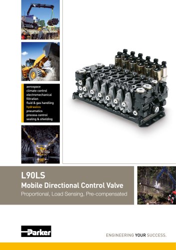 HY17-8504-UK_L90
44 Pages
 HY17-8557-UK_K170
24 Pages
 Y14
Y142 Pages
 HY17-8702-UK_PLC
12 Pages
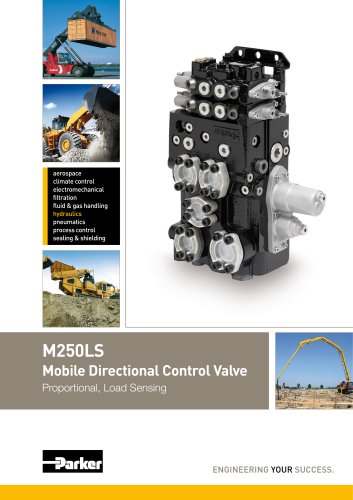 HY17-8562-UK_M250LS
24 Pages
 7-EN%205150-B%20-%20CAR.
15 Pages
 Cover
Cover2 Pages
 HY14-3000FrtCvr
2 Pages
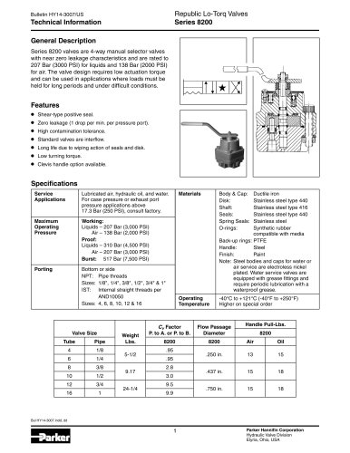 20Lo-Torq
2 Pages

Archived catalogs
 HY17-8356-UK_VP04
12 Pages
 Natural Gas Solutions
12 Pages


- Chiller
- Parker cartridge filter
- Filter cartridge
- Liquid recirculation chiller
- Industrial use filter
- Pressure separator filter
- Stainless steel pre-filter
- Industrial filter cartridge
- Fine filter cartridge
- Filtration unit
- Water recirculation chiller
- Automatic test kit
- Industrial cooling system
- Water filter cartridge
- Parker compressed air dryer
- Compact recirculation chiller
- Plastic filter cartridge
- General purpose filter cartridge
- Nitrogen generator
- Parker gas filter