Catalog excerpts

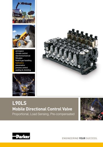
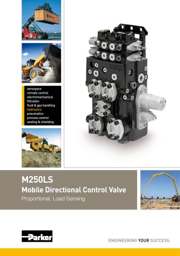
Mobile Directional Control Valve Proportional, Load Sensing, Pre-compensated ENGINEERING YOUR SUCCESS.
Open the catalog to page 1
Catalogue Information Mobile Directional Control Valve Catalogue layout In addition to general information and basic technical data, this catalogue contains descriptions of the many optional functions you can specify for the L90LS, so that we may customize it to control your machine optimally. Each function area of the valve is given as a subheading, followed by a brief description. When different options are avail- able for a function area, the subheading is followed by an item number in square brackets, e.g. Pressure relief valve [16]. This is followed by a series of coded options, e.g....
Open the catalog to page 2
catalogue HY17-8504/UK Mobile Directional Control Valve Contents Page Remote-controlled actuators, proportional spool actuators with open spool-end.. 23 [00] refererar till positionsnummer i kundspecifikationen Parker Hannifin Mobile Controls Division Europe Borâs, Sweden
Open the catalog to page 3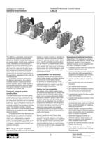
General Information Mobile Directional Control Valve load-sensing, pressure-compensated directional valve for mobile machines such as cranes, skylifts, forklift trucks, platform trucks, excavators and harvesters. It is designed for working pressures of up to 320 bar and a maximum pump flow of 200 l/min.The valve can be given excel- lent simultaneous-operating character- istics, which enable several machine functions to be operated responsively at the same time, regardless of the sizes of individual loads. To facilitate precise customization of wholly modular construction. Each valve is...
Open the catalog to page 4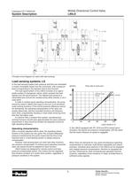
System Description Mobile Directional Control Valve Principle circuit diagram for valve with load sensing. Load sensing systems, LS In the load sensing system both pressure and flow are modulated to match immediate needs from the consumers, with a pressure level corresponding to the heaviest load at that moment. The load signal system of the L90LS consists of an appro- priate number of changeover valves, which compare the load signals from the spool sections. The highest load pressure is transmitted and controls the variable pump either directly or via a copy spool. In order to achieve good...
Open the catalog to page 5
Technical Data Mobile Directional Control Valve Spool actuator C[50] Spool actuator ECH[50] Pump unloading function BEN[22] Tank connection Main pressure relief valve Pump connection Service port connection B, Pilot pressure supply for external use, PS. Connection to external pilot oil filter YS[39]. Pilot pressure supply R[37] Service port connection A, Separate tank connection for Pump connection -Tank connection _Tank connection LS connection from parallel Port relief valve [76] * Stated pressures are absolute shock pressures, valid for grey / nodular iron. Flow rates, recommended Pump...
Open the catalog to page 6
Technical Data Mobile Directional Control Valve Oil temperature, working range Hydraulic fluids Best performance is obtained using mineral-base oil of high quality and cleanness in the hydraulic system. Hydraulic fluids of type H LP (DIN 51524), oil for automatic gearboxes Type A and engine oil type API CD can be used. Viscosity, working range 15-380 mm2/s** Technical information in this catalogue is applicable at an oil viscosity of 30 mm2/s and temperature of 50 C using nitrile rubber seals. * Performance efficiency will be reduced if outside the ideal values. These extreme conditions...
Open the catalog to page 7
Hydraulic circuits Mobile Directional Control Valve L90LS with levers for direct spool actuation and equipped with bypass for systems fed by pumps with fixed displacement. L90LS with electro-hydraulic remote-controlled spool actuators pilot-oil supply counter pressure function, section-specific pres- and equipped with direct-acting main pressure relief valve for sure compensators, port-specific feed reducing valves, port-relief systems fed by LS pumps, pump-unloading function, integrated and anti-cavitation valves, etc. Parker Hannifin Mobile Controls Division Europe Borás, Sweden
Open the catalog to page 8
Hydraulic circuits Mobile Directional Control Valve Hydraulic circuit diagram showing basic functions of L90LS. The item numbers in the hydraulic circuit diagram and table below refer to the valve function areas for which different options are available. The valve in the example above is equipped according to the description below. For other equip- ment alternatives, see under respective valve-function area [Item number] in catalogue. 15 CFC Inlet with bypass for systems with fixed pump. 16 PS Pilot-operated main pressure relief valve. 20 KB Prepared for load-signal copying. 22 BEN...
Open the catalog to page 9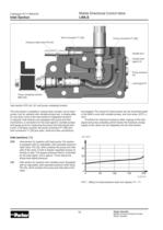
Inlet Section Mobile Directional Control Valve Pressure relief valve PS [16] Gauge port:: Copied load Pump pressure Pump unloading function Inlet section CFC alt. LS1 with pump unloading function. The inlet section is available in several basic variants; one for fixed pumps, four for systems with variable pumps and a simple plate for use when none of the inlet section's integrated functions is required. Inlet sections are equipped with pump and tank connections, a connection for the load signal to variable pumps and gauge ports for measuring the pump and load-signal pres- sures. In all...
Open the catalog to page 10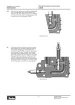
Inlet Section Mobile Directional Control Valve LS2 Inlet section for systems with variable pump. Equipped with a non-adjustable, direct-acting pressure relief valve, PA1 [16], which protects the pump and inlet side of the valve. The LS2 variant is normally equipped with a copy function for the load signal, KS [20]. AS Inlet section with flow distribution function for systems with variable pump. The section distributes the pump flow between activated spool sections fitted with compensator type KAS [66], at maximum flow take-off from the pump. With other inlet types, the consumer working the...
Open the catalog to page 11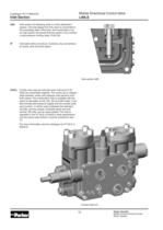
Inlet Section Mobile Directional Control Valve AS2 Inlet section for following valve in a flow distribution system. The load signal from this valve is connected to the preceding valve. Otherwise, the functionality is as for inlet section AS except that the section only contains a load pressure limiting valve, PLM [16]. IP Inlet plate without functions. Contains only connections for pump, tank and load signal. CA/CL Combo inlet used as mid-inlet when L90 and K170/ K220 are assembled together. This works as an adapter plate between valves and replaces inlet sections from both valves. The...
Open the catalog to page 12All Parker Industrial Gas Filtration and Generation Di catalogs and technical brochures
-
HY17-8356-UK_VP04
12 Pages
-
HY17-8542-UK_QDS6
8 Pages
-
HY17-8602-UK_VV6
8 Pages
-
HY17-8557-UK_K170
24 Pages
-
Y14
2 Pages
-
HY17-8702-UK_PLC
12 Pages
-
HY17-8562-UK_M250LS
24 Pages
-
7-EN%205150-B%20-%20CAR.
15 Pages
-
Cover
2 Pages
-
HY14-3000FrtCvr
2 Pages
-
HY17-8534-UK_F130
32 Pages
-
20Lo-Torq
2 Pages
Archived catalogs
-
Natural Gas Solutions
12 Pages

