- Catalogs
- Parker Industrial Gas Filtration and Generation Di
- bulletins%5D/Bul%20HY14-2405-B1%20CFQ
bulletins%5D/Bul%20HY14-2405-B1%20CFQ
1 /3Pages
bulletins%5D/Bul%20HY14-2405-B1%20CFQ
1 /3Pages
Catalog excerpts

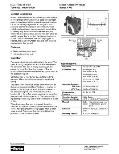
Technical Information Mobile Accessory Valves General Description Series CFQ flow controls are priority type flow controls. A constant rate of flow (through a spool type compen- sator) is maintained at the constant flow port (marked CF on the casting) regardless of changes in load pressure located downstream. Once maximum con- trolled flow is achieved, the compensator spool shifts to delivery any excess flow to an excess flow port (marked EX on the casting). Excess flow can either be used to supply flow to another function or be directed to tank. Should the excess flow port be plugged or blocked, the CFQ will function as a two-port pressure compensated flow control. • Electro-nickeless plated spool • High-tensile cast iron body Flow enters the inlet port and travels to the spool. The spool is spring compensated and is normally open to the controlled flow port. A rotary lever adjusts the amount of controlled flow. Any amount of flow in excess of the controlled flow is diverted by the spool to the excess flow port. Controlled flow is maintained by a 3.4 Bar (50 PSI) pressure differential in the compensator spool and The rotary lever rotates an orifice which increases or decreases the controlled flow. The lever is marked in gradients of 0 through 12. At 0, all flow is directed to the excess flow port. The controlled flow port is blocked. At 1, the orifice begins opening the controlled flow port until it is fully open at 12. The numbers (1-12) represent position only and do not correspond to a rate When the excess flow port is plugged, the valve functions as a pressure compensated flow control. The excess flow port should not be plugged when a relief valve is used. The excess flow port should then be plumbed to tank to vent the relief. Parker Hannifin Corporation Hydraulic Valve Division
Open the catalog to page 1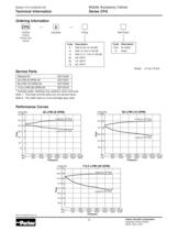
Technical Information Mobile Accessory Valves Ordering Information Priority Flow Service Parts Code Description * Includes seals, retaining ring, washers, lever and knob Note 1 : The body and the spool are not service items Note 2: The relief valve is a non-cartridge type valve Relief Option Code Description Performance Curves Parker Hannifin Corporation Hydraulic Valve Division
Open the catalog to page 2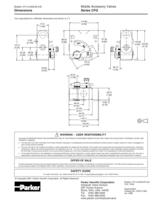
Mobile Accessory Valves Inch equivalents for millimeter dimensions are shown in i A WARNING - USER RESPONSIBILITY FAILURE OR IMPROPER SELECTION OR IMPROPER USE OF THE PRODUCTS DESCRIBED HEREIN OR RELATED ITEMS CAN CAUSE DEATH, PERSONAL INJURY AND PROPERTY DAMAGE. • This document and other information from Parker-Hannifin Corporation, its subsidiaries and authorized distributors provide product or system options for further investigation by users having echnical expertise. • The user, through its own analysis and testing, is solely responsible for making the final selection of the system and components...
Open the catalog to page 3All Parker Industrial Gas Filtration and Generation Di catalogs and technical brochures
 HY17-8542-UK_QDS6
8 Pages
 HY17-8602-UK_VV6
8 Pages
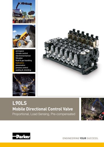 HY17-8504-UK_L90
44 Pages
 HY17-8557-UK_K170
24 Pages
 Y14
Y142 Pages
 HY17-8702-UK_PLC
12 Pages
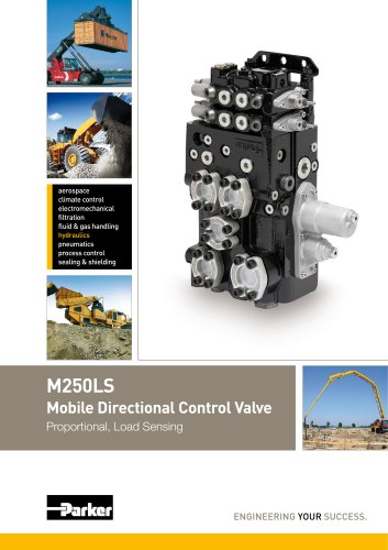 HY17-8562-UK_M250LS
24 Pages
 7-EN%205150-B%20-%20CAR.
15 Pages
 Cover
Cover2 Pages
 HY14-3000FrtCvr
2 Pages
 HY17-8534-UK_F130
32 Pages
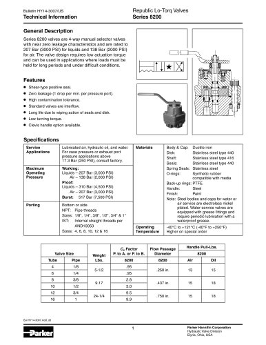 20Lo-Torq
2 Pages

Archived catalogs
 HY17-8356-UK_VP04
12 Pages
 Natural Gas Solutions
12 Pages


- Chiller
- Parker cartridge filter
- Filter cartridge
- Liquid recirculation chiller
- Industrial use filter
- Pressure separator filter
- Stainless steel pre-filter
- Industrial filter cartridge
- Fine filter cartridge
- Filtration unit
- Water recirculation chiller
- Automatic test kit
- Industrial cooling system
- Water filter cartridge
- Parker compressed air dryer
- Compact recirculation chiller
- Plastic filter cartridge
- General purpose filter cartridge
- Nitrogen generator
- Parker gas filter