- Catalogs
- Parker Hannifin France SAS
- Parker Hydraulic Threaded Cartridge Valves


- Company
- Products
- Catalogs
- News & Trends
- Exhibitions
Parker Hydraulic Threaded Cartridge Valves

Parker Hydraulic Threaded Cartridge Valves
This document provides an overview of Parker Hydraulic Threaded Cartridge Valves, detailing product offerings, specifications, and technical guidelines. It emphasizes user responsibility in selecting and using these products to prevent potential hazards.
The catalog includes various types of valves such as check valves, shuttle valves, load/motor controls, flow controls, pressure controls, logic elements, directional controls, solenoid valves, and proportional valves. Each section provides detailed specifications, performance parameters, and application guidelines.
Key specifications include pressure ratings, flow rates, and operational parameters. The document outlines hydraulic formulas for system calculations and provides viscosity guidelines for optimal performance. Pressure ratings are specified for continuous duty, with considerations for material impact on performance.
Check valves are detailed with specifications such as flow capacity and pressure ratings. The catalog includes various types like ball type and poppet type, each with specific applications and performance characteristics.
These valves allow for electrically adjustable hydraulic control, suitable for applications like hoist and winch speed control. The operation involves solenoid coils that adjust the spool position based on electrical input.
The Super Coil series features integral Deutsch connectors, waterproof and thermal shock-resistant designs, and universal operation capabilities. Specifications include wattage options and coil types.
The catalog provides technical tips for each product section, offering insights into application and operational parameters. Users are encouraged to consult these tips for optimal product selection and application.
Detailed ordering information is provided, including model codes and specifications for selecting the appropriate valve body or solenoid coil.
This catalog serves as a comprehensive guide for selecting and applying Parker's hydraulic cartridge valves, emphasizing the importance of adhering to technical specifications and safety guidelines.
This section outlines the pressure ratings and thermal shock resistance of the valves, ensuring they meet specific operational standards.
Details the components and services associated with the valves, emphasizing durability and reliability.
Discusses the operational limitations of the valves, including temperature and pressure constraints.
Guidance on selecting appropriate seal materials based on application requirements, including temperature and fluid compatibility.
Recommends suitable hydraulic fluids and filtration standards to maintain system efficiency and longevity.
Provides insights into the practical applications of the valves in various hydraulic systems.
Offers technical advice on the installation and maintenance of check valves, including new product features and common options like seal types and crack pressure settings.
Describes different types of check valves, such as poppet and ball types, and their specific applications in hydraulic circuits.
Includes detailed specifications for various valve models, highlighting flow rates, pressure ratings, and material compatibility.
Introduces new additions to the check valve product line, focusing on design improvements and enhanced features.
The document provides detailed technical specifications and features of various check valves and shuttle valves manufactured by Parker Hannifin Corporation. These valves are used in hydraulic systems to control flow and pressure.
The document outlines specifications for different series of valves, including rated flow, maximum inlet pressure, leakage rates, pilot ratios, and operating temperature ranges. For example, the CVH201P series check valve has a rated flow of 303 LPM (80 GPM) and a maximum inlet pressure of 350 Bar (5000 PSI).
Common features across the valves include hardened, precision-ground parts for durability, fully guided poppets for smooth operation, and zinc-plated external parts for corrosion resistance. Some valves also feature internal pilot positions to simplify manifold design.
The document includes performance curves showing the relationship between pressure drop and flow rate through the valves, which are critical for understanding valve performance under different operating conditions.
Detailed ordering information is provided, including model numbers, port sizes, body materials, and seal options. Preferred options are highlighted for shorter lead times.
The valves are suitable for use in load sensing circuits, brake circuits, and other hydraulic applications requiring precise flow and pressure control.
Additional technical tips are referenced for further information on valve operation and installation.
This document is a technical catalog from Parker Hannifin Corporation, detailing various hydraulic valves including shuttle valves, check valves, load/motor controls, flow controls, pressure controls, logic elements, directional controls, solenoid valves, proportional valves, coils, and electronics. The catalog provides specifications, features, applications, and ordering information for different valve series.
The catalog describes several series of shuttle valves, including KSWA3, CSH041, CSH101B, and K04C3. Each series is detailed with specifications such as rated flow, maximum inlet pressure, leakage rates, material composition, operating temperature ranges, fluid compatibility, and filtration requirements. Key features include compact design, durability, contamination tolerance, and zinc-plated external parts. Applications typically involve hydraulic oil systems.
KSWA3 Series: Rated flow of 9.5 LPM, maximum pressure of 420 Bar, minimal leakage, and hardened steel parts. CSH041 Series: Rated flow of 3.8 LPM, maximum pressure of 345 Bar, rapid response to load changes. CSH101B Series: Rated flow of 38 LPM, maximum pressure of 350 Bar, precision ground parts. K04C3 Series: Rated flow of 100 LPM, maximum pressure of 420 Bar, high flow capacity.
The document includes performance curves showing pressure drop versus flow for each valve series, providing insights into their operational efficiency under different conditions.
Each valve series includes ordering codes for seals and body materials, with preferred options highlighted for shorter lead times. Additional options may be available with extended lead times.
The catalog provides guidance on selecting counterbalance valves, explaining their operation, applications, and benefits such as controlling overrunning loads, metering applications, and protecting against hose failures. It emphasizes the importance of understanding valve operation and selecting the appropriate valve for specific applications.
This document provides technical information on Parker's load and motor control valves, focusing on counterbalance valves used in hydraulic systems. It covers various series of valves, their specifications, and selection criteria.
Parker offers several series of counterbalance valves, including MHC, CB101, and E2 Series. These valves are designed for integration into manifolds or direct installation into actuator ports. They come in different configurations, such as vented and non-vented, with various flow rates and pilot ratios.
Key factors in selecting a counterbalance valve include flow selection, vented versus non-vented configurations, pilot ratio, and adjustment type. The document emphasizes the importance of sizing the valve according to actual flow rather than system flow to maintain control and stability.
The pilot ratio affects the pressure needed to unseat the poppet. A higher pilot ratio results in less restriction and control, while a lower ratio provides more control and requires more horsepower.
Valves are available with adjustable and non-adjustable pressure settings. Non-adjustable versions are recommended to prevent tampering.
The document outlines three basic settings: holding setting, thermal setting, and pilot area. The holding setting is the maximum load the valve can hold, while the thermal setting compensates for oil expansion due to temperature changes.
Counterbalance valves are used in motor circuits to prevent overrunning loads and cavitation. They require mechanical brakes to hold the load, and vented spring cavities are necessary for closed-loop circuits.
The document discusses the use of equal area counterbalance valves in brake applications to avoid wear. These valves open only when pilot pressure exceeds the valve setting, independent of the load.
The document provides detailed specifications for the E2E1, E2K1, and E2M1 valve series, including rated flow, pressure, pilot ratio, and material composition.
Information on ordering valves, including pilot ratio, adjustment style, and seal options, is provided. Preferred options are highlighted for shorter lead times.
This document provides technical specifications and features of various series of load control and counterbalance valves designed for motion control applications. These valves are pilot-assisted and incorporate features such as poppet construction for minimal leakage, direct acting relief valves for overload protection, and reverse check valves to save space and minimize installation costs. The valves are designed to be mounted directly into cylinders, eliminating the need for a manifold block.
The valves operate within a temperature range of -34°C to +121°C for Nitrile seals and -26°C to +204°C for Fluorocarbon seals. They are compatible with mineral-based or synthetic fluids with viscosities ranging from 45 to 2000 SSU (6 to 420 cSt). Filtration requirements are ISO-4406 18/16/13, SAE Class 4. The valves are made of steel with hardened operating parts for durability.
Rated flow varies across models, with some handling up to 60 LPM (16 GPM). Pressure ratings range from 40 to 420 Bar (580 to 6000 PSI). Pilot ratios available include 1.5:1, 3:1, 4.5:1, 7:1, and 10:1, providing flexibility for different applications. The valves feature a sealed spool type design for improved stability and accuracy, and low leakage poppet-type check valves for reliable load holding. External parts are zinc plated for corrosion resistance.
The document provides detailed ordering codes for different valve series, specifying options for pilot ratios, adjustment styles, seals, and body materials. Preferred options are highlighted for shorter lead times.
The document includes performance curves illustrating relief performance, pressure drop versus flow, and required piloted pressure calculations for various valve models.
For further technical details, the document refers to additional technical tips and sections within the catalog.
This document provides detailed technical specifications and ordering information for various series of Load Control Valves by Parker Hannifin Corporation. These valves are designed for motion control applications and feature a threaded cartridge style with pilot assistance.
- Rated Flow: Ranges from 20 LPM (5.3 GPM) to 180 LPM (48 GPM) depending on the series.
- Pressure: Operates between 50 to 420 Bar (725 to 6000 PSI).
- Temperature Range: -34°C to +121°C for Nitrile seals and -26°C to +204°C for Fluorocarbon seals.
- Fluid Compatibility: Suitable for mineral-based or synthetic fluids with viscosities of 45 to 2000 SSU (6 to 420 cSt).
- Filtration: ISO-4406 18/16/13, SAE Class 4.
- Spring chamber isolated from system backpressure by double seal.
- Poppet construction for minimal leakage.
- Direct acting relief valve for overload protection.
- Reverse check valve included within the body.
- Hardened working parts for maximum durability.
- All external parts are zinc plated.
The document includes performance curves illustrating the relationship between flow rate and pressure drop for different valve series, highlighting relief and pilot performance.
Each valve series has specific ordering codes that denote pilot ratio, adjustment style, seals, and body material. Preferred options are highlighted for shorter lead times.
Dimensions are provided in millimeters and inches, with torque specifications for installation. Separate ordering for valve bodies is required, with details available in section BC.
The document serves as a comprehensive guide for selecting and ordering Load Control Valves, providing essential technical data and performance insights for optimal application in hydraulic systems.
This document provides technical insights into Parker Hannifin Corporation's line of Flow Control Valves, detailing their specifications, operations, and applications. It aims to assist in selecting the appropriate valve for specific applications.
Parker offers four primary adjustment types for flow control valves:
- Screw Adjustment: Commonly used, adjustable with an allen wrench, includes a lock nut.
- Knob Adjustment: Features an aluminum knob for easier adjustments, with a lock knob to maintain settings.
- Fixed Style: Preset at the factory, adjustable by removing components.
- Tamper Resistant: Concealed adjustment with a steel cap, preset at the factory.
Valves use a 4301 Polyurethane “D”-Ring, eliminating the need for backup rings. Options for Nitrile or Fluorocarbon seals are available, depending on temperature and fluid compatibility.
Some needle valve series offer fine meter needles for finer control in small flow ranges, reducing maximum flow capacity.
Various flow control products are available, with specific options detailed in individual valve model pages.
- Needle Valve: Provides uncompensated adjustable flow control, ideal for general hydraulic flow control.
- Needle with a Reverse Check: Offers adjustable speed control in one direction and free flow in the opposite.
- P.C. Flow Regulator: Maintains regulated flow regardless of pressure changes, suitable for actuator control.
- P.C. Flow Control: Pressure compensated with a reverse flow check valve, providing constant regulated flow.
- Priority Style P.C. Flow Regulator: Maintains constant priority flow, diverting excess flow for other uses.
- Flow Divider/Combiner: Proportions flow from a single source into two actuators or combines flow from two sources.
Details on the Needle Valve Series NVH081 include:
- Rated Flow: 37.9 LPM (10 GPM)
- Maximum Inlet Pressure: 380 Bar (5500 PSI)
- Operating Temperature Range: Varies by seal type, from -37°C to +204°C
- Fluid Compatibility: Suitable for mineral-based or synthetic fluids with specific viscosities
- Filtration: ISO-4406 18/16/13, SAE Class 4
The document provides technical specifications and operational details for Parker Hannifin's Flow Divider/Combiner Valve, Series L06A3. This spool-type valve is designed for equal control in dividing or combining flows, with pressure compensation in both directions. It is commonly used in transmission applications for differential lock.
- Interlocking spools for equal control
- Range of flow settings for optimized control
- Pressure compensated control
- Standard 50/50 ratio, with other ratios available
- Hardened parts for durability
- Zinc-plated external parts
- Rated Flow: 180 LPM (47 GPM)
- Maximum Inlet Pressure: 420 LPM (6000 PSI)
- Accuracy Per Leg: ±10%
- Operating Temperature Range: -34°C to +121°C (Nitrile), -26°C to +204°C (Fluorocarbon)
- Fluid Compatibility: Mineral-based or synthetic with viscosities of 45 to 2000 SSU
- Filtration: ISO-4406 18/16/13, SAE Class 4
- Approx. Weight: 0.40 kg (0.86 lbs.)
The document includes ordering information for different seal types and flow ratings, with highlighted options for shortest lead times. It specifies the cavity and port size for installation.
This section introduces Parker's pressure control valves, highlighting new products and design features. It discusses common options like adjustment types and seal compatibility, emphasizing the importance of matching seals to application conditions.
- Direct Acting Relief Valves: Fast response for intermittent duty, suitable for clipping pressure spikes.
- Differential Area Relief Valves: Best for fast response in intermittent applications, handling larger flow rates.
- Pilot Operated Relief Valves: Designed for continuous duty, offering stability and low pressure rise for hydraulic system pressure setting.
The document provides detailed technical information on various types of hydraulic valves, including dual crossover relief valves, pilot-operated reducing valves, unloading relief valves, pressure reducing/relieving valves, sequence valves, and direct acting relief valves. Each section includes specifications, operational descriptions, and features.
This document is a technical catalog from Parker Hannifin Corporation, detailing various hydraulic valve products including check valves, shuttle valves, load/motor controls, flow controls, pressure controls, logic elements, directional controls, solenoid valves, proportional valves, coils, and electronics. The focus is on direct acting relief valves and differential area relief valves.
- Specifications: Available in pressure ranges of 6.9-69 Bar, 13.8-207 Bar, and 13.8-345 Bar. Standard settings are 34.5 Bar, 103.5 Bar, and 172.4 Bar respectively.
- Features: Hardened, precision ground parts, internal mechanical stop, spherical poppets, zinc-plated external parts, and fast response.
- Ordering Information: Options for screw adjust style, with separate ordering for bodies. Seals available in D-Ring, Nitrile, and Fluorocarbon.
- Specifications: Rated flow of 38 LPM, maximum inlet pressure of 250 Bar, and maximum pressure setting of 210 Bar. Sensitivity varies with pressure range.
- Features: Similar to RDH101 with additional emphasis on low leakage and durability.
- Ordering Information: Pressure ranges of 7-62 Bar, 13.8-124 Bar, and 41.4-207 Bar. Standard settings are 31.0 Bar, 62.1 Bar, and 103.4 Bar respectively.
- Specifications: Rated flow of 100 LPM, maximum inlet pressure of 420 Bar, and maximum pressure setting of 420 Bar.
- Features: Fast response, virtually leak-free, hardened parts, and zinc-plated external parts.
- Ordering Information: Pressure ranges of 5-210 Bar and 5-420 Bar. Standard settings are 100 Bar and 200 Bar respectively.
- Specifications: Rated flow of 45 LPM, maximum inlet pressure of 380 Bar, and maximum pressure setting of 350 Bar.
- Features: High flow capacity, low leakage, and durable construction.
- Ordering Information: Pressure ranges of 6.9-103 Bar, 69-207 Bar, and 138-345 Bar. Standard settings are 51.7 Bar, 103 Bar, and 172.4 Bar respectively.
- Specifications: Rated flow of 75 LPM, maximum inlet pressure of 380 Bar, and maximum pressure setting of 350 Bar.
- Features: Similar to RDH083 with additional emphasis on high flow capacity and low leakage.
- Ordering Information: Pressure ranges of 6.9-69 Bar, 34.5-207 Bar, and 34.5-345 Bar. Standard settings are 34.5 Bar, 103.5 Bar, and 172.4 Bar respectively.
This document provides detailed technical information on various hydraulic valves manufactured by Parker Hannifin Corporation, specifically focusing on tamper-resistant versions. The catalog includes specifications, features, and ordering information for different series of relief valves.
- Specifications: Rated flow of 151 LPM (40 GPM), maximum inlet pressure of 240 Bar (3500 PSI), and maximum pressure setting of 210 Bar (3000 PSI). Operating temperature ranges from -34°C to +121°C with Nitrile seals and -26°C to +204°C with Fluorocarbon seals.
- Features: Hardened, precision-ground parts for durability, compact size, low leakage design, and fast response. All external parts are zinc plated.
- Ordering Information: Available in screw adjust style with pressure ranges of 13.8 - 69 Bar and 41.4 - 207 Bar. Bodies and seals are ordered separately.
- Specifications: Rated flow of 75.8 LPM (20 GPM), maximum inlet pressure of 350 Bar (5000 PSI), and maximum pressure setting of 350 Bar (5000 PSI). Operating temperature ranges from -37°C to +93°C with "D"-Ring seals.
- Features: Low profile adapter, fully guided pilot, and internal screening for debris protection. Steel adapters are zinc plated.
- Ordering Information: Available in screw adjust style with pressure ranges of 6.9 - 69 Bar, 13.8 - 207 Bar, and 13.8 - 345 Bar. Bodies and seals are ordered separately.
- Specifications: Rated flow of 113 LPM (30 GPM), maximum inlet pressure of 350 Bar (5000 PSI), and maximum pressure setting of 350 Bar (5000 PSI). Operating temperature ranges from -37°C to +93°C with "D"-Ring seals.
- Features: Low profile adapter, fully guided poppet, and internal screening for debris protection. Steel adapters are zinc plated.
- Ordering Information: Available in screw adjust style with pressure ranges of 6.9 - 69 Bar, 13.8 - 207 Bar, and 13.8 - 345 Bar. Bodies and seals are ordered separately.
- Specifications: Rated flow of 189.5 LPM (50 GPM), maximum inlet pressure of 380 Bar (5500 PSI), and maximum pressure setting of 350 Bar (5000 PSI). Operating temperature ranges from -34°C to +121°C with Nitrile seals.
- Features: Ball-type pilot for stability, high accuracy, and compact size. All external parts are zinc plated.
- Ordering Information: Available in screw adjust style with pressure ranges of 6.9 - 69 Bar, 20.7 - 207 Bar, and 34.5 - 345 Bar. Bodies and seals are ordered separately.
- Specifications: Rated flow of 302.8 LPM (80 GPM), maximum inlet pressure of 380 Bar (5500 PSI), and maximum pressure setting of 350 Bar (5000 PSI).
- Features: Low profile adapter, fully guided poppet, and internal screening for debris protection. Steel adapters are zinc plated.
This document provides technical specifications and operational details for Parker Hannifin Corporation's pressure reducing/relieving valves, specifically the PRH101 and PRH161 series. It includes information on valve features, performance curves, specifications, and ordering details.
The PRH101 series is designed for a rated flow of 56.3 LPM (15 GPM) with a maximum inlet pressure of 380 Bar (5500 PSI) and a maximum pressure setting of 350 Bar (5000 PSI). The PRH161 series supports a higher rated flow of 151.4 LPM (40 GPM) under the same pressure conditions. Both series are compatible with mineral-based or synthetic fluids with viscosities ranging from 45 to 2000 SSU (6 to 420 cSt).
Key features include hardened, precision-ground parts for durability, low-profile adapters for space efficiency, fully guided poppets for consistent reseating, and zinc-plated steel adapters. The valves also incorporate a polyurethane "D"-Ring to eliminate backup rings and prevent hydrolysis, along with internal screening to protect the pilot spring from debris.
The document includes performance curves illustrating flow versus regulated pressure and pressure versus flow through the cartridge. These curves are essential for understanding the valve's behavior under different operational conditions.
The document outlines the ordering codes for different pressure ranges and adjustment styles. The PRH101 and PRH161 series offer screw adjust options, with pressure ranges from 13.7 to 345 Bar (200 to 5000 PSI) and standard settings provided for each range.
Parker's logic valves are highlighted as versatile components for system designers, offering poppet and spool types for various applications. Poppet types are used for flow switching and directional control, while spool types are used for pressure sensing and flow regulation.
The document discusses the use of poppet logic valves for uni-directional and bi-directional flow switching, as well as spool type logic valves for modulating applications such as pressure relief and flow control.
This document provides technical specifications and ordering information for various hydraulic valves and components manufactured by Parker Hannifin Corporation. It includes details on logic elements, directional control valves, and pilot-operated spool valves.
- Weight: 0.14 kg (0.3 lbs) for certain components.
- Materials: All parts are made of steel with hardened steel for operating parts. External parts are zinc plated.
- Operating Temperature Range: Varies by seal type: -37°C to +93°C for D-Ring, -34°C to +121°C for Nitrile, and -26°C to +204°C for Fluorocarbon.
- Fluid Compatibility: Suitable for mineral-based or synthetic fluids with viscosities of 45 to 2000 SSU (6 to 420 cSt).
- Filtration: ISO-4406 18/16/13, SAE Class 4.
- 3-Way Pilot Operated Spool Valve (DH103 Series): Used in normally closed or open directional control circuits requiring remote pilot actuation. It directs flow alternately from either side of a closed loop transmission for cooling or filtering.
- Directional Control Valves (Series N5A125 and N5A300): These are pilot-operated, 3-way, 2-position valves with external drain and open transition. They are designed for high flow capacity and can be used as switching or metering elements.
- DH103 Series: Rated flow of 38 LPM (10 GPM) with a maximum inlet pressure of 345 Bar (5000 PSI). Leakage is 50 cc/min at 240 Bar (3500 PSI).
- N5A125 Series: Rated flow of 160 LPM (42 GPM) with a maximum inlet pressure of 420 Bar (6000 PSI).
- N5A300 Series: Similar high flow capacity with detailed performance curves provided for pressure drop versus flow.
The document provides codes for ordering different configurations, including bias spring codes, seal types, and body materials. Preferred options are highlighted for shorter lead times.
The document outlines the specifications for directional valves, including rated flow of 400 LPM (105 GPM) and nominal flow at 7 Bar (100 PSI) of 270 LPM (71 GPM). The maximum inlet pressure is 420 Bar (6000 PSI). The operating temperature range for Nitrile seals is -34°C to +121°C, and for Fluorocarbon seals, it is -26°C to +204°C. The fluid compatibility includes mineral-based or synthetic fluids with viscosities of 45 to 2000 SSU (6 to 420 cSt). Filtration requirements are ISO-4406 18/16/13, SAE Class 4.
The document provides codes for ordering different components of the valve, such as seals (Nitrile or Fluorocarbon), switching pressure (6.9 Bar or 10.0 Bar), and body material (Steel). It highlights preferred options for shorter lead times.
Common options for solenoid valves include seals, coils, manual overrides, and screens. Seals are available in Nitrile or Fluorocarbon, and coils can be ordered separately with various terminations and voltages. Manual overrides allow for valve operation without coil force, and screens provide cursory protection against debris.
The document describes two-way poppet valves, which are pilot-operated and low leakage, suitable for single operation actuators or unloading functions. Normally closed poppet valves block flow when de-energized, while normally open poppet valves allow free flow. Free reverse flow and fast response options are available for specific applications. Two-way spool valves are direct-acting and fast-responding, blocking flow from both the side port and the nose port.
The document provides technical specifications and features of various series of 2-way poppet valves, including DSH121, DSH161, DSL201, DSL087, and GS02 81. These valves are designed for hydraulic systems and are characterized by their replaceable coils, various manual override options, and zinc-plated external parts.
- DSH121 Series: Rated flow of 90 LPM (24 GPM) with a maximum inlet pressure of 350 Bar (5000 PSI). Operating temperature ranges from -34°C to +121°C with Nitrile seals and -26°C to +204°C with Fluorocarbon seals.
- DSH161 Series: Rated flow of 150 LPM (40 GPM) with similar pressure and temperature specifications as the DSH121 series.
- DSL201 Series: Rated flow of 260 LPM (70 GPM) with a maximum inlet pressure of 250 Bar (3600 PSI).
- DSL087 Series: Rated flow of 1.1 LPM (0.3 GPM) with a maximum input pressure of 250 Bar (3600 PSI).
The document includes performance curves illustrating the relationship between pressure drop and flow rate for each valve series, using hydraulic oil at 150 SSU @ 100°F (32 cSt).
- Low hysteresis and minimal amperage draw.
- Various coil terminations and voltages available.
- Manual override options include push and twist mechanisms.
- Encapsulated coils and zinc-plated external parts for durability.
Each valve series has specific ordering codes for size, style, seals, and override options. Coils are sold separately, and additional details can be found in the catalog sections referenced.
For further technical details, the document refers to technical tips on pages SV2-SV6. The valves are compatible with mineral-based or synthetic fluids with viscosities ranging from 45 to 2000 SSU (6 to 420 cSt) and require filtration according to ISO 4406 18/16/13, SAE Class 4 standards.
This document provides technical specifications and ordering information for a series of bi-directional poppet type, 2-way valves from Parker Hannifin Corporation. These valves are used in hydraulic systems and are available in normally closed and normally open configurations.
- Rated Flow: Varies by model, with flows ranging from 19 LPM (5 GPM) to 285 LPM (75 GPM).
- Maximum Inlet Pressure: 350 Bar (5000 PSI) for all models.
- Leakage: 5 to 9 drops/minute at 150 SSU (32 cSt).
- Operating Voltage: Minimum 85% of rated voltage at 20°C (72°F).
- Response Time: Typically 40 ms for opening and closing, with specific times detailed in performance curves.
- Material: All parts are made of steel, with operating parts hardened.
- Operating Temperature Range: -34°C to +121°C for Nitrile seals, -26°C to +204°C for Fluorocarbon seals.
- Fluid Compatibility: Suitable for mineral-based or synthetic fluids with viscosities of 45 to 2000 SSU (6 to 420 cSt).
- Filtration: ISO 4406 18/16/13, SAE Class 4.
- Built-in thermal relief set at 36 Bar (500 PSI) above rated pressure.
- One-piece cartridge housing ensures internal concentricity.
- Waterproof, hermetically sealed coil that requires no O’Rings and is interchangeable with other series.
The document includes performance curves showing pressure drop versus flow and response time versus flow for different valve configurations.
The document provides detailed ordering codes for different valve configurations, including options for seals, screen, and manual override. Coils are sold separately, and specific part numbers for seal kits are provided.
Detailed dimensions are provided in both millimeters and inches for installation and compatibility purposes.
This document provides technical specifications and performance data for Parker Hannifin's Series DSH083, DSH103, and DSH084 hydraulic spool valves. These valves are designed for high flow capacity with minimal space requirements and feature standard valve bodies and common cavities.
- DSH083 Series: 3-way solenoid valves with options for manual override. Available in various configurations (A, B, C, N) with different flow paths and pressure drop characteristics. Maximum operating pressure is 5000 PSI.
- DSH103 Series: 3-way spool valves with high flow capacity. Rated flow varies by configuration (A, B, N) with maximum inlet pressure of 350 Bar (5000 PSI). Operating temperature ranges from -37°C to +204°C depending on seal material.
- DSH084 Series: 4-way spool valves with performance curves provided. Rated flow is 11-15 LPM with a maximum inlet pressure of 350 Bar (5000 PSI).
- Encapsulated coil design for minimal amperage draw.
- Manual overrides and seal variations available.
- Polyurethane “D”-Ring eliminates the need for backup rings.
- Nylon inserted jam-nut for secure holding in high vibration applications.
- All external parts are zinc plated for corrosion resistance.
- Pressure drop vs. flow graphs are provided for each valve series, illustrating performance with hydraulic oil at 150 SSU @ 100°F (32 cSt).
- Shift limit characteristics are detailed, showing minimum operating voltage requirements for different flow paths.
Valves are available in different sizes and configurations, with separate ordering for coils and valve bodies. Preferred options are highlighted for shorter lead times.
- Operating Voltage: Minimum 85% of rated voltage at 20°C (72°F).
- Response Time: Energized - 50 ms, De-energized - 30 ms.
- Cartridge Material: All parts are steel, with all operating parts made of hardened steel.
- Operating Temperature Range/Seals:
- “D”-Ring: -37°C to +93°C (-35°F to +200°F)
- Nitrile: -34°C to +121°C (-30°F to +250°F)
- Fluorocarbon: -26°C to +204°C (-15°F to +400°F)
- Fluid Compatibility/Viscosity: Mineral-based or synthetic with lubricating properties at viscosities of 45 to 2000 SSU (6 to 420 cSt).
- Filtration: ISO 4406 18/16/13, SAE Class 4.
- Approximate Weight: 0.13 kg (0.29 lbs.).
- Cavity: C08-4 (See BC Section for more details).
Catalog MSG15-3504 by Parker Hannifin Corporation, HVS and MSDE Divisions, covers various valve types including check valves, shuttle valves, load/motor controls, flow controls, pressure controls, logic elements, directional controls, solenoid valves, proportional valves, coils, and electronics.
- Series DSH084: Spool Type, 4-Way Valve with dimensions provided in millimeters and inches. Ordering information includes solenoid valve style and override options.
- Series DSH104: Features high flow capacity, standard valve bodies, encapsulated coil, and various seal options. Performance curves and pressure drop vs. flow data are provided.
- Series DSH164: Pilot operated spool type valve with high flow capacity and pressure capability. Requires a pressure differential for operation.
- Series GS02 51: 4-Way, 3 Position, Closed Center Spool Valve designed for double acting cylinders and bi-directional motors. Features high flow capacity and pressure capability.
- Coils are sold separately, with specific sections in the catalog for ordering information.
- Various seal options are available, including D-Ring, Nitrile, and Fluorocarbon, with corresponding kit part numbers.
- Manual override options are available for certain models.
The document details the specifications for a series of 4-way solenoid valves, specifically the GS04 series. The rated flow is 42 LPM (11 GPM) with a maximum inlet pressure of 350 Bar (5000 PSI) and a maximum tank pressure of 210 Bar (3000 PSI). Leakage is specified at 160 cc/min at 210 Bar with a viscosity of 150 SSU (32 cSt). The operating temperature range varies depending on the seal material: -34°C to +121°C for Nitrile and -26°C to +204°C for Fluorocarbon. The valves are compatible with mineral-based or synthetic fluids with viscosities from 45 to 2000 SSU (6 to 420 cSt). Filtration requirements are ISO 4406 18/16/13, SAE Class 4.
The document outlines the ordering information for the valves, including options for seals, style, screen, override options, and design level. It specifies that coils are sold separately and provides details on the preferred options for shortest lead times.
The valves are designed to operate double-acting cylinders and bi-directional motors. They feature a one-piece cartridge housing for internal concentricity and a waterproof, hermetically sealed coil that requires no O-rings. The symmetrical coil can be reversed without affecting performance. Performance curves are provided, showing flow rates and pressure drops under various conditions.
For optimal performance, it is recommended to maintain the operating voltage at a minimum of 85% of the rated voltage at 20°C. The document also suggests using the specified filtration standards to ensure the longevity and efficiency of the valves.
The document includes detailed technical data, such as dimensions, torque specifications, and part numbers for seal kits. It also provides information on the cavity and port sizes, as well as the materials used for the valve bodies.
This document provides technical insights into Parker Hannifin's line of Proportional Valves, detailing their specifications, operations, and applications. It aims to assist in selecting the appropriate valve for specific applications by explaining common options and technical terms.
The document outlines the importance of seal compatibility with temperature and fluid types, and the role of overrides in valve operation. Key technical terms include Ohm’s Law, Pulse Width Modulation (PWM), hysteresis, and deadband, which are crucial for understanding valve performance and control.
Proportional valves are electrically adjustable hydraulic valves offering infinite control and flexibility. They include flow control, pressure reducing, and relief valves. Applications range from hoist control to winch speed regulation. The document describes the operation of normally closed and open proportional flow control valves, highlighting their pseudo pressure compensation capabilities.
These valves allow electronic control of flow, with normally closed versions opening with increased current and normally open versions closing with increased current. The document explains the operation and compensation mechanisms of these valves.
These valves electronically reduce inlet pressure and act as relief valves. The document details the operation of pilot-operated versions, which are slower but can handle high pressures.
Proportional relief valves control system pressure electronically. Normally closed versions default to maximum pressure without current, while normally open versions default to minimum pressure. The document explains their operation and pressure setting mechanisms.
The document includes performance curves for proportional relief valves, illustrating pressure versus input signal and pressure drop versus flow. These curves are essential for understanding valve behavior under different conditions.
This document provides technical specifications and ordering information for various series of proportional relief valves and a proportional pressure reducing/relief valve, manufactured by Parker Hannifin Corporation. The valves are designed for precise pressure control in hydraulic systems.
- Rated Flow: Varies by model, with values such as 3.0 LPM (0.8 GPM) for 21C and 1.3 LPM (0.35 GPM) for 35C at 70 PSI ΔP.
- Maximum Pressure: Up to 350 Bar (5000 PSI) for certain models.
- Hysteresis: Typically around 5% at 200 Hz PWM for some models.
- Operating Temperature Range: Varies with seal type, from -37°C to +204°C.
- Fluid Compatibility: Suitable for mineral-based or synthetic fluids with viscosities of 45 to 2000 SSU.
- Filtration: ISO-4406 18/16/13, SAE Class 4.
- Proportional relief valves are pilot-operated or direct-acting, with pressure output proportional to DC current input.
- Coils are waterproof and hermetically sealed, requiring no O-rings.
- Some models feature low hysteresis and high flow capacity, with a preference for 400 Hz PWM signals.
The document includes performance curves illustrating the relationship between pressure, flow, and input current for various models, highlighting the valves' efficiency and response times.
Details on ordering include size, maximum relief settings, and seal options. Coils and bodies are sold separately, with specific sections of the catalog referenced for additional information.
These valves are suitable for use in hydraulic systems requiring precise pressure control, such as in load/motor controls, flow controls, and pressure controls.
This document provides technical specifications and ordering information for Parker Hannifin's proportional directional control valves, specifically the GP02 and DSP105 series. It includes details on valve dimensions, ordering codes, and application circuits.
The GP02 series offers standard and high flow options with manual override capabilities. The DSP105 series features a 4-way, 3-position valve with closed or floating center spools. Operating pressure is up to 210 Bar (3000 PSI), with a temperature range for various seals from -37°C to +204°C.
The valves are designed with a one-piece cartridge housing for internal concentricity, waterproof coils, and zinc-plated external parts. The coils are hermetically sealed and can be reversed without affecting performance.
Valves are available in different sizes and configurations, with separate ordering for coils and bodies. Preferred options are highlighted for shorter lead times.
The document includes guidance on coil selection, emphasizing continuous duty operation and the importance of correct termination to prevent damage. It also discusses the use of diodes for surge protection and the availability of AC and DC coil versions.
Performance curves are provided for different configurations, showing flow rates and pressure drops under various conditions. The document advises on derating performance for continuous duty applications.
Parker Hannifin Corporation's catalog MSG15-3504 provides detailed information on various hydraulic components including check valves, shuttle valves, load/motor controls, flow controls, pressure controls, logic elements, directional controls, solenoid valves, proportional valves, coils, and electronics. The catalog is divided into sections that cover technical data, specifications, and ordering information for each product type.
The catalog details the Super Coil Series, available in 1/2” and 5/8” I.D. sizes. Key features include:
- Integral Deutsch connector coil exceeding IP69K standards.
- Thermal shock dunk test rated.
- Universal 50/60 Hz operation.
- Hermetically sealed coils requiring no O-rings or waterproofing kits.
- External plated steel flux-carrying band for thermal shock resistance.
- Symmetrical design allowing reversible installation without performance impact.
For the 5/8” I.D. Super Coil:
- Nominal wattage: 18W (Standard), 28W (Puissant).
- Continuous duty cycle at 100% voltage.
- Temperature range: -40°C to +200°C.
- Encapsulating material: Glass-filled rynite.
- Nominal wattage: 14W.
- Lead wire: 22 gauge, 24” long.
- Encapsulating material: Glass-Filled Polyethylene Terephthalate (PET).
Coils are available with different termination options including DIN 43650, Integral Deutsch with Anti-vibration ring, and Zener Diode configurations. Additional voltages and terminals may be available upon request.
The catalog provides an index of standard and special bodies and cavities, detailing sizes and configurations for various applications. Features include:
- Lightweight aluminum bodies for low pressure applications.
- Durable steel bodies for higher pressures, coated with zinc for corrosion resistance.
- Various port sizes and types available.
This section offers guidance on the application of Parker Hannifin's products, highlighting the features of standard line bodies and common cavities, and providing insights into material choices and construction benefits.
The document provides technical specifications and guidelines for Parker Hannifin Corporation's hydraulic valve bodies and cavities, focusing on materials, porting options, pressure drop considerations, and valve/cavity compatibility.
Parker offers valve bodies in both aluminum and steel. Aluminum bodies are anodized for corrosion resistance but are not suitable for applications above 210 bar (3000 psi). Steel bodies are more durable and are coated with zinc for enhanced corrosion resistance, particularly against salt spray.
Various port sizes and types are available, with a recommendation for SAE ports over NPT or pipe ports due to their secure connections. The document notes a change in port numbering for 3-way line bodies to reduce confusion.
The pressure drop through a line body is minimal, and each catalog page includes a pressure drop curve to help estimate total pressure drop when combined with the cartridge.
The document explains the concept of 'common' cavities, which allow for interchangeability of valves from different manufacturers, though caution is advised regarding cross drill ports and thread depths. A compatibility chart is provided to identify which valves can fit into existing cavities.
The chart helps determine if a valve from one manufacturer can be replaced by another, indicating compatibility across Parker, Waterman, FPS, and CEC products.
Detailed dimensions and performance curves for various sizes and configurations of valve bodies and cavities are provided, including pressure drop versus flow data.
Not all cartridge options are endurance tested; some are validated by design similarity. Only one three-way spool is tested, with others assumed similar.
Operating limits range from -30°C to 150°C. Performance may vary at extremes, affecting leakage and response. Seal temperature limits are specified for different materials like Nitrile, Fluorocarbon, Hytrel, GTPFE, and Polyurethane.
Ideal viscosity range is 15 to 50 cSt. Performance decreases outside this range, requiring user evaluation for suitability.
Continuous duty pressure ratings are catalog-based. Material choice affects pressure recommendations, with aluminum bodies not recommended above 207 bar.
Rapid temperature changes can affect product performance and lifespan.
Integrated hydraulic circuits are serviceable by replacing valves. External components like coils and seals are available, but internal parts are not.
Not recommended for on-highway, aerospace, explosive transport, or hazardous environments.
Parker offers Polyurethane, Nitrile, and Fluorocarbon seals. The "D"-Ring is standard, offering better wear resistance and tensile strength.
Use high-quality mineral or synthetic fluids with viscosities of 45 to 2000 SSU. Fluids should have anti-wear properties and oxidation protection.
Maintain ISO cleanliness level of 18/16/13 to prevent contamination, which causes 75% of system failures.
Ensure correct valve installation by verifying part numbers. Fit interchangeability does not guarantee functional interchangeability.
Parker Hannifin Corporation provides contact details for various divisions and support services.
Catalog excerpts
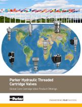
Parker Hydraulic Hydraulic Threaded Threaded Parker Cartridge Cartridge Valves Valves Global Core Core Cartridge Global CartridgeValve ValveProduct ProductOfferings Offerings
Open the catalog to page 1
! WARNING - USER RESPONSIBILITY FAILURE OR IMPROPER SELECTION OR IMPROPER USE OF THE PRODUCTS DESCRIBED HEREIN OR RELATED ITEMS CAN CAUSE DEATH, PERSONAL INJURY AND PROPERTY DAMAGE. This document and other information from Parker-Hannifin Corporation, its subsidiaries and authorized distributors provide product or system options for further investigation by users having technical expertise. The user, through its own analysis and testing, is solely responsible for making the final selection of the system and components and assuring that all performance, endurance, maintenance, safety and warning...
Open the catalog to page 2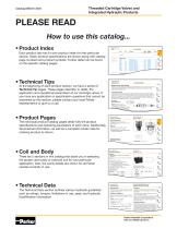
Threaded Cartridge Valves and Integrated Hydraulic Products PLEASE READ How to use this catalog... • Product Index Check Valves Each product tab has it’s own product index for that particular section. Basic product specifications are shown along with catalog page numbers and product symbols. Further detail can be found on the specific catalog pages. FLOW LPM/GPM PRESSURE BAR/PSI Check Valves Load/Motor Controls Flow Controls PILOT OPERATED CHEC • Technical Tips Technical Tips At the beginning of each product section, we have a series of Technical Tip pages. These pages describe, in detail, the...
Open the catalog to page 3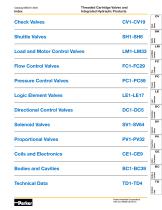
Threaded Cartridge Valves and Integrated Hydraulic Products Check Valves Check Valves Shuttle Valves Shuttle Valves Load and Motor Control Valves Load/Motor Controls Proportional Valves Technical Data Pressure Controls Logic Elements Solenoid Valves Directional Control Valves Solenoid Valves Logic Element Valves Proportional Valves Pressure Control Valves Coils & Electronics Flow Control Valves Flow Controls Technical Data Parker Hannifin Corporation HVS and MSDE Divisions
Open the catalog to page 4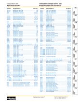
Threaded Cartridge Valves and Integrated Hydraulic Products Parker Hannifin Corporation HVS and MSDE Divisions Check Valves Shuttle Valves Load/Motor Controls Alphabetical Index
Open the catalog to page 5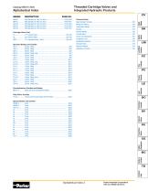
Threaded Cartridge Valves and Integrated Hydraulic Products Check Valves Shuttle Valves Alphabetical Index Load/Motor Controls Solenoid Valves Proportional Valves Coils & Electronics Bodies & Cavities Technical Data Parker Hannifin Corporation HVS and MSDE Divisi
Open the catalog to page 6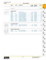
Check Valves Check Valves Load/Motor Controls Flow Controls PRESSURE BAR/PSI Pressure Controls FLOW LPM/GPM Logic Elements SERIES CAVITY DESCRIPTION Solenoid Valves Proportional Valves Coils & Electronics Bodies & Cavities Technical Data Parker Hannifin Corporation HVS and MSDE Divisions
Open the catalog to page 7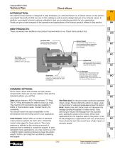
Technical Tips Check Valves Dual Sense Paths The dual sense paths reduce the pressure drop variations. Spherical Poppets The spherical design allows for a more consistent seating regardless of poppet alignment resulting in lower leakage. Shuttle Valves There are several new additions and product improvements to our Check Valve product line. This technical tips section is designed to help familiarize you with the Parker line of Check Valves. In this section we present the products that are new to this catalog as well as some design features of our checks valves. In addition, we present common...
Open the catalog to page 8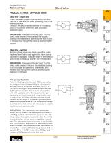
Technical Tips Shuttle Valves Check Valve - Poppet Type Check valves are poppet style elements that allow free flow in one direction while preventing flow in the reverse direction. They can be used to isolate portions of a hydraulic circuit or to provide a free flow path around a restrictive valve. Check Valves PRODUCT TYPES / APPLICATIONS Flow Controls Pressure Controls Check Valve - Ball Type Ball type check valves are check valves that use a hardened steel ball to seal against the valve seat as opposed to a poppet. They are simple in their design and provide low leakage over the life of the...
Open the catalog to page 9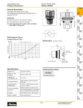
Sense Check Valve Series CVH021 General Description • Rapid response to load direction changes • Hardened precision parts for durability • Insert style design for location within manifolds FREE FLOW CHECKED FLOW Cartridge Style Sense Check Valve. For additional information see Technical Tips on pages CV2-CV3. Check Valves under SAE-6 or larger port Free Flow PC Millimeters (Inches) Pressure Controls Ordering Information Cartridge Material Steel operating parts hardened steel ball. Operating Temp. Range/Seals Fluid Compatibility/ Viscosity Mineral-based or synthetic with lubricating properties...
Open the catalog to page 10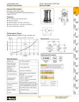
Check Valve Insert, Ball Type Series D1A060 Product Information General Description Check Valves Ball Type, Check Valve Insert. For additional information see Technical Tips on pages CV2-CV3. Shuttle Valves • For inserting inside manifold blocks • High flow capacity • Minimal leakage - less than 3 drops/min. • Simple construction - extremely cost effective • Good contamination tolerance Performance Curve Free Flow Pressure Drop vs. Flow (Through cartridge only) Logic Elements Pressure Controls Ordering Information Check Valve Insert Cracking Pressure Rated Flow Maximum Inlet Pressure Highlighted...
Open the catalog to page 11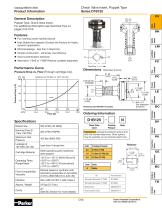
Check Valve Insert, Poppet Type Series D1B125 Product Information General Description Check Valves Poppet Type, Check Valve Insert. For additional information see Technical Tips on pages CV2-CV3. Shuttle Valves • For inserting inside manifold blocks Stable flow capacity (Contact the Factory for Highly • High dynamic application) Flow Controls Millimeters (Inches) Retaining Clip #8010977 Included. 100 Ordering Information Check Valve Insert Rated Flow Maximum Inlet Pressure Less than 3 drops/min. Cartridge Material Steel operating parts hardened steel poppet. Operating Temp. Range/Seals Fluid...
Open the catalog to page 12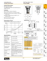
Ball Type, Check Valve Series D02B2 Product Information General Description Check Valves Ball Type Check Valve. For additional information see Technical Tips on pages CV2-CV3. • Good contamination tolerance • All external parts zinc plated Pressure Controls Ordering Information Ball Type Check Valve Highlighted represents preferred options that offer the shortest lead times. Other options may be available, but at extended lead times. Maximum Inlet Pressure Cracking Pressure Less than 3 drops/min. Part Number Solenoid Valves Rated Flow Proportional Valves Cartridge Material Steel operating parts...
Open the catalog to page 13All Parker Hannifin France SAS catalogs and technical brochures
 MPI™ Medium Pressure Products
20 Pages
 Needle Valves
48 Pages
 Phastite® Tube Connectors
36 Pages
 Quick Coupling Products
230 Pages
 Ball and Plug Valves
72 Pages
 Aluminium Roller Guides
20 Pages
 OSPP-Classic
37 Pages
 Valve Products Isys ISO Series
42 Pages
 2A Pneumatic Cylinders
48 Pages
 Stainless Steel Valves
72 Pages
 Global FRL and P3Y Series
122 Pages
 MMB Hydraulic Cylinders
24 Pages
 PWO Water/oil cooler
12 Pages
 Axial Piston Pumps
28 Pages
 QDC - Quiet DC Cooler
56 Pages
 Air Oil Coolers
18 Pages
 Hydraulic Valves Industrial Standard
817 Pages
 Quick Couplings Catalog
185 Pages
 Crankcase Ventilation
12 Pages
 Condition Monitoring
72 Pages
 Screw-Driven Positioners
111 Pages
 Belt Driven Positioners
151 Pages
 GVI Global Vehicle Inverter
16 Pages
 GVM142 Global Vehicle Motor
16 Pages