
- Catalogs
- Parker Hannifin France SAS
- P1/PD Series Medium Pressure Axial Piston Pumps


- Company
- Products
- Catalogs
- News & Trends
- Exhibitions
P1/PD Series Medium Pressure Axial Piston Pumps

P1/PD Series Medium Pressure Axial Piston Pumps
The P1/PD Series of medium pressure axial piston pumps by Parker Hannifin are designed for variable displacement in open-circuit applications. They operate continuously at pressures up to 280 bar and are available in high drive speed models for mobile markets and low noise models for industrial markets. Key features include quiet and efficient control capability, compact size, high power density, and modular controls for easy conversions. The pumps are equipped with elastomer seals to eliminate gaskets and external leakage, and they offer fast and stable compensator response.
The ordering code for the P1/PD Series includes options for shaft type, rotation, seal material, and mounting pad & coupling. Various configurations are available to suit different applications, including mobile (P1) and industrial (PD) models.
The document provides detailed specifications for shaft options, including torque ratings and load ratings. Maximum input shaft torque varies by model, with the highest being 1701 Nm for the 140cc model. Radial and axial shaft load ratings are also specified.
Control options include pressure limiters, load sensing, and electronic displacement controls. Additional options such as cam sensors and unload valves are available for specific control configurations.
Performance data includes typical pump outlet flow, shaft input power, shaft bearing life, and noise characteristics. These metrics are crucial for assessing the suitability of the pump for specific applications.
Dimensional data is provided for each model in the series, detailing the physical dimensions and mounting configurations.
Guidelines for installation are provided to ensure optimal performance and longevity of the pumps.
The document includes conversions and formulas to assist in the calculation of various parameters related to pump operation.
The offer of sale section outlines the terms and conditions under which the pumps are sold by Parker Hannifin and its distributors.
A warning is included emphasizing the user's responsibility to ensure proper selection and use of the pumps to prevent injury or damage.
- Pressure Limiter Control (C): Limits maximum system pressure with an adjustment range of 26-280 bar. The pump achieves full displacement unless restricted by system valves or maximum pressure is reached.
- Load Sensing and Pressure Limiter (L): Matches pump flow and pressure to system demands, reducing horsepower losses. It features a differential adjustment range of 10-40 bar.
- Remote Operated Pressure Limiter (AM): Allows remote adjustment of the pressure compensator setting via a relief valve connected to the control.
- Torque Limiting Controls (AMT, ANT, L0T): Combine pressure limiting with torque limiting to manage input torque under varying power demands.
- Electronic Proportional Pressure Limiting (AE, AF): Integrates a proportional relief valve for electronic adjustment of pressure settings, with options for 12VDC and 24VDC solenoids.
- Electronic Unload/Cold Start (C03, C06, L03, L06): Features an unload function to reduce torque during cold starts by de-stroking the pump.
- Electronic Proportional Displacement & Pressure Limiting (P, T, S, U): Uses electronic proportional valves to control displacement and pressure, with options for minimum or maximum displacement defaults.
- Typical control response times are provided for various pump models, indicating the time taken to transition between maximum and zero displacement.
- Graphs illustrate the relationship between system pressure and displacement or torque settings, highlighting the pump's performance under different conditions.
- Pressure settings and control options are based on NFPA testing standards.
- Electrical characteristics for solenoids and proportional valves are detailed, including voltage, coil resistance, and maximum current specifications.
For optimal performance, ensure proper configuration of control options based on specific application requirements. Consult Parker Hannifin for additional driver options and technical support.
- The pumps require a sequence valve in the pressure line or an external servo source for proper operation. Without adequate servo pressure, the pump defaults to stroke.
- A mechanical pressure limiter can override electronic inputs to cap the pump outlet pressure at a preset level.
- Electronic control allows the pump to operate in an overcenter condition, useful for applications like energy recovery.
- Response times vary by displacement, with times ranging from 35 ms to 109 ms for zero to max and max to zero transitions.
- Parameters for 12 VDC and 24 VDC systems include resistance, max current, PWM signal frequency, and typical hysteresis.
- Connectors and wiring details are provided for displacement sensors.
- Graphs illustrate pump outlet flow and shaft input power across various displacements and speeds, with data provided for different pump models (e.g., P1/PD 018, 028, 045, etc.).
- Flow rates and power input are measured at a 50°C inlet oil temperature using ISO VG32 fluid.
- Shaft bearing life is depicted in terms of L-10 and B-10 life expectancy under different duty cycle pressures.
- Sound pressure levels are measured under anechoic conditions, with data provided for zero and full flow scenarios across various pump models.
- Spline Details: The document outlines specifications for involute splines, including the number of teeth, pitch, pressure angle, major and pitch diameters. For example, the SAE 32-4 (C) spline has 14 teeth, a pitch of 12/24, and a pressure angle of 30°.
- Port Sizes: The pumps feature various port configurations, including SAE flanged, metric flanged, and BSPP ports. The document specifies dimensions for inlet and outlet ports, such as the "A" inlet being 2" Code 61 for SAE flanged ports.
- Installation Notes: The document provides installation notes for different control options ("L" or "AM") and specifies that SAE flanged ports conform to SAE J518, while metric flanged ports conform to ISO 6162.
- The document references several standards, including ANSI B92.1-1996 for splines and SAE J744 for mounting dimensions.
- It is recommended to adhere to the specified dimensions and standards for optimal performance and compatibility.
Catalog excerpts

P1/PD Series Medium Pressure Axial Piston Pumps Variable Displacement Catalog HY28-2665-01/P1/EN Effective: August 2021 | Replaces April 2021
Open the catalog to page 1
Axial Piston Pumps P1/PD Series WARNING - USER RESPONSIBILITY FAILURE OR IMPROPER SELECTION OR IMPROPER USE OF THE PRODUCTS DESCRIBED HEREIN OR RELATED ITEMS CAN CAUSE DEATH, PERSONAL INJURY AND PROPERTY DAMAGE. This document and other information from Parker-Hannifin Corporation, its subsidiaries and authorized distributors provide product or system options for further investigation by users having technical expertise. The user, through its own analysis and testing, is solely responsible for making the final selection of the system and components and assuring that all performance, endurance,...
Open the catalog to page 2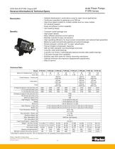
Axial Piston Pumps P1/PD Series General Information & Technical Specs Description • Variable displacement, axial piston pump for open-circuit applications • Continuous operation at pressures up to 280 bar • High drive speed models for mobile markets and low noise models for industrial markets • Quiet and efficient control capability • Cam bearing design Compact overall package size High power density Many different standard control options Modular controls for easy conversions High operating efficiency for lower power consumption and reduced heat generation Elastomer seals that eliminate gaskets...
Open the catalog to page 3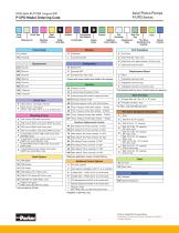
Axial Piston Pumps P1/PD Series P1/PD Model Ordering Code Circuit Type Mounting & Ports Shaft Options Single Shaft Seal Fluorocarbon Seal Material Pump Family Controls Design Series L0 Load sensing & pressure limiter Open Circuit - One Side of Center Open Circuit - Overcenter (45-75, 100-140cc with P, T, S, U controls only) SAE mount; SAE work & aux ports SAE mount; Metric work ports; BSPP aux ports ISO mount; Metric work & aux ports ISO mount; Metric work ports; BSPP aux ports 2-bolt SAE C mount; SAE work & aux ports (60-85cc only) 2-bolt SAE C mount; metric work ports; BSPP aux ports (60-85cc...
Open the catalog to page 4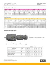
Axial Piston Pumps P1/PD Series Model Code Descriptions Mounting Designation Descriptions Code Shaft Descriptions Code SAE-BB keyed SAE-BB keyed SAE-C keyed SAE-C keyed SAE-CC keyed SAE-D keyed Maximum Flange Moment Ratings Maximum Static Moment Maximum Dynamic Moment (at 10g acceleration) Distance L1 (no thru drive) Distance L1 (thru drive) Parker Hannifin Corporation Hydraulic Pump and Power Systems Division United States
Open the catalog to page 5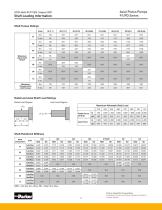
Axial Piston Pumps P1/PD Series Shaft Loading Information Shaft Torque Ratings 01 02 04 Maximum Input shaft torque Maximum through-drive shaft torque ft.lbs Nm ft.lbs Nm ft.lbs Radial and Axial Shaft Load Ratings Radial Load Diagram Axial Load Diagram Maximum Allowable Shaft Load Axial Force ft-lb/Rad Nm/Rad ft-lb/Rad Nm/Rad NRD = No rear thru drive; RD = Rear thru drive Parker Hannifin Corporation Hydraulic Pump and Power Systems Division United States
Open the catalog to page 6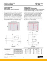
Axial Piston Pumps P1/PD Series Controls Information Control Option “C” The "C0" pressure limiter control is used to limit the maximum system pressure. The control acts such that full pump displacement is achieved unless the system valve restricts the output flow or the load pressure reaches the maximum setting of the control. If pump flow is restricted by the system valve, the pump will provide only the flow demanded, but at the maximum pressure setting of the compensator control. If the outlet flow is completely blocked, the pump will destroke to zero displacement and maintain the pressure...
Open the catalog to page 7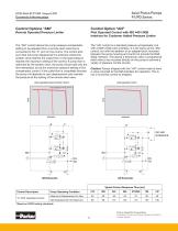
Axial Piston Pumps P1/PD Series Controls Information The "AM" control allows the pump pressure compensator setting to be adjusted from a remote relief valve that is connected to the "X" port on the control. The control acts such that full pump displacement is achieved unless the system valve restricts the output flow or the load pressure reaches the maximum setting of the control. If pump flow is restricted by the system valve, the pump will provide only the flow demanded, but at the maximum pressure setting of the compensator control. If the outlet flow is completely blocked, the pump will destroke...
Open the catalog to page 8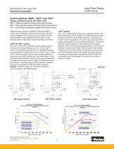
Axial Piston Pumps P1/PD Series Controls Information Torque Limiting Controls: (45-140cc only) AMT = Remote pressure limiting with torque limiting ANT = Pilot operated pressure limiting with torque limiting L0T = Load sense & pressure limiting with torque limiting "L0T" Control These controls provide the benefit of pressure limiting control, plus the ability to limit the input torque when the power available from the prime mover is limited; or when the application power demand has both high flow/low pressure and low flow/high pressure operating conditions. The "L0T" combines the functions of...
Open the catalog to page 9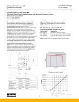
Axial Piston Pumps P1/PD Series Controls Information Electronic Proportional Pressure Limiting with Mechanical Pressure Limiter Minimum Pressure Default AE = 12 VDC Solenoid AF = 24 VDC Solenoid Note: The pressure relief valve has a command range up to 350 bar, but P1/PD pump is rated to 280 bar continuous pressure. This control is the same as the AN control, but with the proportional relief valve included. It allows the pump pressure compensator setting to be adjusted by an on-board 4VP0150G24B1C1 (24V) or RE06M35W2N1KWXG087 (12V) proportional, electronic relief valve. The control acts such...
Open the catalog to page 10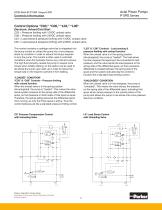
Axial Piston Pumps P1/PD Series Controls Information Electronic Unload/Cold Start C03 = Pressure limiting with 12VDC unload valve C06 = Pressure limiting with 24VDC unload valve L03 = Load sense & pressure limiting with 12VDC unload valve L06 = Load sense & pressure limiting with 24VDC unload valve “L03” & “L06” Controls - Load sensing & pressure limiting with unload function When the unload valve is in the spring position (de-energized), the pump is “loaded”. The load sense function requires the signal port be connected to load pressure, and the valve sends the load pressure to the spring side...
Open the catalog to page 11All Parker Hannifin France SAS catalogs and technical brochures
 MPI™ Medium Pressure Products
20 Pages
 Needle Valves
48 Pages
 Phastite® Tube Connectors
36 Pages
 Quick Coupling Products
230 Pages
 Ball and Plug Valves
72 Pages
 Aluminium Roller Guides
20 Pages
 OSPP-Classic
37 Pages
 Valve Products Isys ISO Series
42 Pages
 2A Pneumatic Cylinders
48 Pages
 Stainless Steel Valves
72 Pages
 Global FRL and P3Y Series
122 Pages
 MMB Hydraulic Cylinders
24 Pages
 PWO Water/oil cooler
12 Pages
 Axial Piston Pumps
28 Pages
 QDC - Quiet DC Cooler
56 Pages
 Air Oil Coolers
18 Pages
 Hydraulic Valves Industrial Standard
817 Pages
 Quick Couplings Catalog
185 Pages
 Crankcase Ventilation
12 Pages
 Condition Monitoring
72 Pages
 Screw-Driven Positioners
111 Pages
 Belt Driven Positioners
151 Pages
 GVI Global Vehicle Inverter
16 Pages
 GVM142 Global Vehicle Motor
16 Pages





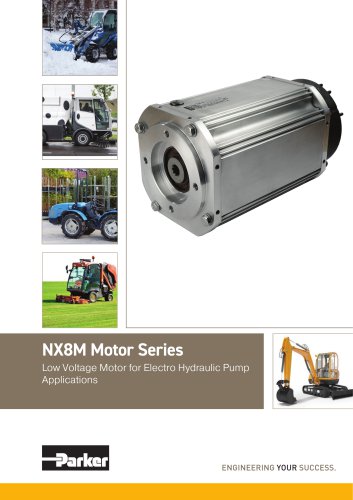
- Electromotor
- Parker piping
- Parker manual valve
- Display module
- Control valve
- Parker stainless steel valve
- Flowmeter
- Parker hydraulic fitting
- Parker water valve
- Parker ball valve
- Parker cylinder
- Parker screw-in fitting
- Synchronous motor
- Pneumatic valve
- Volume flow monitor
- Liquid flow monitor
- Parker pneumatic fitting
- Actuator