
- Catalogs
- Parker Hannifin France SAS
- MPI™ Medium Pressure Products


- Company
- Products
- Catalogs
- News & Trends
- Exhibitions
MPI™ Medium Pressure Products

MPI™ Medium Pressure Products
The MPI™ Presetting Instruction Manual provides comprehensive guidance on installing the MPI™ tube system, which can be assembled manually or with hydraulic presetting equipment. It includes detailed instructions for presetting tubing compatible with MPI™ fittings.
MPI™ fittings and valves adhere to ASME standards B31.1, B31.3, and B31.3 Chapter IX, with a maximum allowable working pressure of 15,000 psi. Engineers must select the appropriate standard for their specific application.
Each MPI™ fitting features corrosion-resistant ferrules, an extended thread area for enhanced pressure resistance, and a molybdenum disulfide-coated nut to prevent galling and allow multiple remakes.
The manual provides details on using MPI™ Body and Nut Dies for small and large preset assemblies, including specific part numbers and dimensions.
Instructions for setting up the MPI™ Air Pump Kit include connecting it to a clean air supply, setting the pump preset pressure, and bleeding air from the hydraulic system. Tables specify preset pressures for various fitting sizes and materials.
Steps involve preparing the tube, inserting it into the preset head, and ensuring proper ferrule seating. The MPI™ Gap Gauge is mandatory for certain sizes to ensure correct assembly.
Similar to the air pump setup, the hand pump requires selecting the correct preset head size and pressure, attaching the preset head, and bleeding air from the system.
Instructions mirror those for the air pump, emphasizing proper ferrule seating and using the MPI™ Gap Gauge to verify correct assembly.
Additional presetting requirements for specific tubing types and the importance of using the MPI™ Gap Gauge for certain sizes are highlighted.
The document outlines assembly and presetting procedures for MPI™ fittings, emphasizing the use of the MPI™ Gap Gauge for sizes 12 and 16. It details hydraulic presetting requirements for Cone and Thread tubing, specifying pressures for different fitting sizes. Instructions for assembling MPI™ fittings to finger tight plus additional turns are provided.
This section describes the assembly process for heavy wall annealed 316 tubing, which can be done by hand or preset. A table lists minimum preset pressures for various fitting sizes, advising on reduced manual makeup and preset pressures to minimize tube swell.
Step-by-step instructions for assembling Parker MPI™ fittings include marking the nut and body to count turns and using the MPI™ Gap Gauge to verify proper nut travel. Hydraulic presetting is highlighted for larger fittings (3/4" and 1"), with remake instructions to ensure proper ferrule seating.
This section offers guidance on pump speed, ferrule rotation, and using diagnostic tools like the Tube Insertion Gauge. It emphasizes proper ferrule seating and the use of the MPI™ Gap Gauge for initial makeup.
The document lists reference torques for different fitting sizes, providing a baseline for checking connections when the original position is not marked.
The document outlines terms and conditions of sale, including price adjustments, delivery dates, warranty details, and liability limitations. It specifies buyer responsibilities and seller rights, including security interests and special tooling charges.
The Buyer must indemnify the Seller against claims or damages from product misuse, negligence, or non-compliance with terms. The Seller is not obligated to indemnify the Buyer unless specified.
Orders cannot be canceled or changed without the Seller's consent. The Seller may alter product features with notice.
The Buyer cannot assign rights or obligations without the Seller's written consent.
This document represents the complete agreement between the Buyer and Seller, superseding all prior agreements.
Non-enforcement of a provision does not waive it. Invalid provisions do not affect the validity of others.
The Seller can terminate the agreement with 30 days' notice or immediately for specific breaches by the Buyer.
The agreement is governed by Ohio law, with disputes resolved in Cuyahoga County courts.
The Seller will defend the Buyer against U.S. intellectual property infringement claims, contingent on timely notification and control over defense.
Prices exclude taxes unless stated otherwise.
For government contracts over $10,000, equal employment opportunity clauses are included.
The document provides contact details for Parker Hannifin Corporation's global offices.
Improper use or selection of products can lead to severe consequences. Users must ensure products meet all application requirements.
Catalog excerpts

MPI™ Medium Pressure Products Air and Hand Pump: Setup and Preset Instructional Manual
Open the catalog to page 1
MPI™ Overview Advanced Features The MPI™ Presetting Instruction Manual documents the proper installation procedures for the MPI™ tube system. Parker MPI™ Fittings can be assembled either manually or by using hydraulic presetting equipment. This manual provides step by step instructions to successfully preset each type of tubing approved for use with MPI™ fittings using either manual or air driven presetting equipment. Every MPI™ Fitting has the features shown below: MPI™ Fittings Pressure Ratings 3. Longer thread area for improved resistance to pressure and load on the ferrules. Parker Hannifin...
Open the catalog to page 3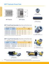
MPI™ Hydraulic Preset Tools Parker Part No. 9 MPI Body Die Adapter MPI™ Nut Die Parker Part No. MPI™ Nut Die Handle MPI™ Small Preset Assembly: Body Dies and Nut Dies Used MPI Small Preset Assembly Parker Part No. MPI™ SMALL Preset Assembly Dimensions in inches are for reference only, subject to change. MPI™ Large Preset Assembly: Body Dies and Nut Dies Used MPI Large Preset Assembly * Requires a 9 MPI Body Die Adapter Dimensions in inches are for reference only, subject to change. Parker Part No. MPI™ AIR PUMP KIT Parker Part No. MPI™ LARGE Preset Assembly Parker Part No. MPI™ HAND PUMP KIT...
Open the catalog to page 4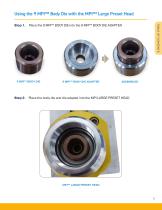
Using the 9 MPI™ Body Die with the MPI™ Large Preset Head Place the 9 MPI™ BODY DIE into the 9 MPI™ BODY DIE ADAPTER 9 MPI™ BODY DIE ADAPTER Step 2. Place the body die and die adapter into the MPI LARGE PRESET HEAD
Open the catalog to page 5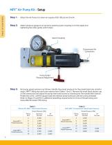
MPI™ Air Pump Kit - Setup Step 1. Attach the Air Pump to a clean air supply of 60-120 psi and 9 scfm. Attach pressure gauge to air pump by pushing quick coupling on to the nipple and tightening the collar gently until it stops. Quick Coupling Pump Outlet Pressure Adjustment Set pump preset pressure as follows. Identify the preset pressure for the preset head size (small or large), MPI™ fitting size and tube material from Tables 1 and 2. Remove the small black plastic cap on the swivel post and adjust the pump relief valve screw by inserting the Tee handle Allen wrench. Rotate the screw until...
Open the catalog to page 6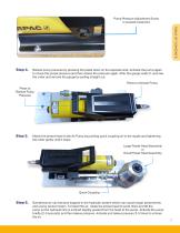
Pump Pressure Adjustment Screw is located inside Nut TA B L E O F C O N T E N T S Relieve pump pressure by pressing the pedal down on the opposite side. Activate the pump again to check the preset pressure and then relieve the pressure again. After the gauge reads 0, unscrew the collar and remove the gauge by pulling straight out. Press to Activate Pump Press to Relieve Pump Pressure Attach the preset head to the Air Pump by pushing quick coupling on to the nipple and tightening the collar gently until it stops. Large Preset Head Assembly or Small Preset Head Assembly Quick Coupling Sometimes...
Open the catalog to page 7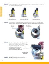
Rotate the Preset Head to point left, right, or up (depending on the desired angle of use) and the ram should rest flat against the pad. Preset Head Angle Left Preset Head Angle Up Insert preset body die into the head with the tapered body seat pointing out. If using the 9 MPI BODY DIE with the LARGE MPI PRESET ASSEMBLY refer to the additional instructions on Page 5. Tapered Body Seat Preset Head Angle Right Body Die Drops into Preset Head Screw the nut die into the preset head until it bottoms firmly against the bottom using the nut die handle. The face of the nut die should be approximately...
Open the catalog to page 8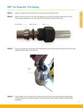
MPI™ Air Pump Kit - Pre-Setting Square cut the end of the tube and remove burrs from tube OD and ID. Slide nut and ferrules onto the tube with tapered end of ferrules pointed toward the end of the tube. (proper sequence is nut, short back ferrule and then longer front ferrule) Front Ferrule Back Ferrule Hold nut and ferrules on the tube while inserting the tube into the head and seat the end of the tube against the tube stop in the body die. Finger tighten (do not wrench) the nut into the nut die until the hex almost bottoms against the nut die. Leaving the nut approximately 1/4 turn from the...
Open the catalog to page 9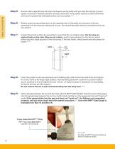
Ensure tube is against body die stop and depress pump pedal until you hear the change in pump speed. Continue to depress pedal for at least 5 seconds. Pump speed should not slow sufficiently at the end of preset that individual strokes can be counted. (A) Relieve pressure by pushing down on the opposite side of the pedal and remove nut/ferrule assembly from the head by rotating the nut out. This should be easily done by hand without the use of a wrench. Inspect the preset nut/ferrule assembly to insure that the nut rotates easily, the ferrules are seated firmly on the tube (they do not rotate),...
Open the catalog to page 10
MPI™ Hand Pump Kit - Setup Based upon the MPI™ fitting size and tube material select the proper preset head size and presetting pressure from Tables 1 and 2. Refer to Pages 15 and 16 for additional presetting requirements for Cone & Thread tubing and Heavy Wall Annealed 316 tubing. TABLE 1 316 and 317 MPI™ Tube Preset Pressure TABLE 2 2507 MPI™ & Instrument Tube Preset Pressure Small MPI™ Preset Assembly Large MPI™ Preset Assembly Fitting Size Standard Ferrules Fitting Size Standard Ferrules Small MPI™ Preset Assembly Large MPI™ Preset Assembly Attach preset head to the Hand Pump by pushing quick...
Open the catalog to page 11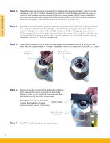
Relieve the reservoir pressure on the pump by rotating the cap approximately 1/4 turn counter clockwise to the “vent” position. Remember to close the cap before transporting the pump or hydraulic fluid can leak from the reservoir. Due to the small volume of fluid used in presetting, the pump can be used with the vent cap in the closed position, but it still should be vented and closed occasionally to relieve pressure due to temperature changes, etc. Sometimes air can become trapped in the hydraulic system which can cause longer preset times and a jerky preset motion. To bleed the air, close the...
Open the catalog to page 12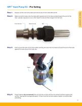
MPI™ Hand Pump Kit - Pre-Setting Square cut the end of the tube and remove burrs from tube OD and ID. Slide nut and ferrules onto the tube with tapered end of ferrules pointed toward the end of the tube. (proper sequence is nut, short back ferrule and then longer front ferrule) Front Ferrule Back Ferrule Hold nut and ferrules on the tube while inserting the tube into the head and seat the end of the tube against the tube stop in the body die. Finger tighten (do not wrench) the nut into the nut die until the hex almost bottoms against the nut die. Leaving the nut approximately 1/4 turn from the...
Open the catalog to page 13All Parker Hannifin France SAS catalogs and technical brochures
 Needle Valves
48 Pages
 Phastite® Tube Connectors
36 Pages
 Quick Coupling Products
230 Pages
 Ball and Plug Valves
72 Pages
 Aluminium Roller Guides
20 Pages
 OSPP-Classic
37 Pages
 Valve Products Isys ISO Series
42 Pages
 2A Pneumatic Cylinders
48 Pages
 Stainless Steel Valves
72 Pages
 Global FRL and P3Y Series
122 Pages
 MMB Hydraulic Cylinders
24 Pages
 PWO Water/oil cooler
12 Pages
 Axial Piston Pumps
28 Pages
 QDC - Quiet DC Cooler
56 Pages
 Air Oil Coolers
18 Pages
 Hydraulic Valves Industrial Standard
817 Pages
 Quick Couplings Catalog
185 Pages
 Crankcase Ventilation
12 Pages
 Condition Monitoring
72 Pages
 Screw-Driven Positioners
111 Pages
 Belt Driven Positioners
151 Pages
 GVI Global Vehicle Inverter
16 Pages
 GVM142 Global Vehicle Motor
16 Pages







- Electromotor
- Parker piping
- Parker manual valve
- Parker stainless steel valve
- Display module
- Control valve
- Flowmeter
- Parker hydraulic fitting
- Parker water valve
- Parker ball valve
- Parker cylinder
- Parker screw-in fitting
- Synchronous motor
- Pneumatic valve
- Volume flow monitor
- Liquid flow monitor
- Parker pneumatic fitting
- Actuator