- Catalogs
- Parker Hannifin France SAS
- Hydraulic Valves Industrial Standard


- Company
- Products
- Catalogs
- News & Trends
- Exhibitions
Hydraulic Valves Industrial Standard

Hydraulic Valves Industrial Standard
- DC Valves: Includes direct and pilot-operated valves with options for proportional control and EtherCAT compatibility. Models like D30FP, D31DW, and D3FB are highlighted.
- Pressure Relief Valves: Covers direct and pilot-operated valves, including proportional and high-performance variants such as R4V and VBY.
- Flow Control Valves: Features 2-way and proportional valves, with models like DUR*L06 and PCMS.
- Check Valves: Includes direct and pilot-operated options with various mounting configurations.
- Throttle Valves: Details proportional and pilot-operated throttle valves, including high-response variants.
- Pressure Reducing Valves: Lists direct and pilot-operated models with proportional options available.
- Proportional Control: Many valves offer proportional control for precise fluid management.
- EtherCAT Compatibility: Select models are compatible with EtherCAT for enhanced communication and control.
- Mounting Options: Various mounting configurations are available, including subplate, pipe, and sandwich plate.
- Certification: Some valves come with TÜV certification, ensuring compliance with safety standards.
- D1SE Series: A 3/2-way seated type directional control valve with a wet pin armature solenoid, compatible with DIN NG06, CETOP 03, and NFPA D03 standards.
- D1VW Series: A directional spool valve available in various configurations, supporting high functional limits up to 80 l/min with low pressure drop.
- D1SE Series: Maximum operating pressure is 350 bar, with a flow rate of 20 l/min.
- D1VW Series: Maximum operating pressure is 350 bar for ports P, A, B, and 210 bar for port T (DC).
- Flow and Pressure: Includes flow curve diagrams and pressure drop data for various spool types and configurations.
- Response Times: Detailed response times for standard and soft shift configurations are provided.
- Design: Directional spool valve with solenoid actuation.
- Size: DIN NG06 / CETOP 03 / NFPA D03.
- Mounting Interface: DIN 24340 A6 / ISO 4401 / CETOP RP 121-H / NFPA D03.
- Operating Pressure: Maximum 350 bar for ports P and A, 210 bar for port T.
- Spool Positions: Various configurations including 2 and 3 position spools with spring offsets.
- Shift Limits: Defined for both DC and AC solenoids.
- Mounting Position: Unrestricted, preferably horizontal.
- Connector Types: Includes EN 175301-803, AMP Junior Timer, and DT04-2P “Deutsch” connectors.
- Design: Directional spool valve with solenoid actuation.
- Size: DIN NG10 / CETOP 05 / NFPA D05.
- Mounting Interface: Compatible with DIN 24340 A10, ISO 4401, CETOP RP 121-H, NFPA D05.
- Operating Pressure: Maximum 350 bar for P, A, B ports; 210 bar for T port (DC), 105 bar (AC).
- Duty Ratio: 100% ED with a maximum coil temperature of 150°C.
- Switching Frequency: Up to 10,000 cycles per hour.
- Viscosity Range: Permitted 2.8 to 400 cSt, recommended 30 to 80 cSt.
- Filtration: ISO 4406 (1999); 18/16/13.
- Soft shift anchor tubes for smooth operation.
- Position control and additional surface protection available.
- Shift limits are specified for both DC and AC solenoids.
- Used in safety-relevant applications with monitored start or end positions.
- Protection Class: IP65 as per EN 60529 with correctly mounted plug-in connector.
- Ambient Temperature: -20 to +60°C.
- Supply Voltage: 10-30 V with a ripple of ±10%.
- Minimum distance to the next AC solenoid is 0.1 meters.
- Position control is monitored via inductive switches for start and end positions.
- Flow versus pressure drop curves are provided for various spool types.
- Design: Directional spool valve with solenoid actuation, size DIN NG10 / CETOP 05 / NFPA D05.
- Various spool positions and types are available, with specific codes for solenoid options and voltage requirements.
- Energy-saving A-regeneration function.
- Switchable hybrid version for different operational modes.
- Design: Directional spool valve actuated by solenoid.
- Mounting Interface: Complies with DIN 24340 and ISO 4401 standards.
- Operating Pressure: Maximum of 350 bar for most configurations.
- Spool Types: Various configurations available.
- Solenoid Options: Available with or without manual override.
- Mounting Position: Unrestricted, though horizontal is preferred.
- Design: Direct operated proportional DC valve with position feedback and pilot operated DC valve.
- Actuation: Proportional solenoid.
- Max Operating Pressure: 350 bar for ports P, A, B; 35 bar for port T.
- Duty Ratio: 100%.
- ProPxD Interface Program: Allows parameter setting and storage for module electronics.
- Design: Direct operated servo proportional DC valve with VCD® actuator.
- Max Operating Pressure: 350 bar for ports P, A, B; 250 bar for external drain.
- Supply Voltage: 22 to 30 V DC.
- Real servovalve dynamics with a frequency response of 200 Hz.
- Direct Operated Proportional DC Valve (Series D*FP*D): Features include frequency response, pressure gain, and flow curves.
- For safety-related systems, the valve electronics voltage supply should be switched off by a reliable switching element when the safety function is requested.
- The ProPxD software facilitates the configuration of valve parameters.
- Details are provided for different valve series.
- Includes information on spool position, command signal, seals, connection type, and electronics options.
- General design and hydraulic specifications are provided.
- Frequency response and flow curves are provided for different spool types and command signals.
1. Environmental Conditions: The ambient temperature range is -20 to +50°C. The Mean Time To Failure (MTTFD) is 75 years.
2. Physical Characteristics: The weight varies from 11.3 kg to 64.5 kg depending on the model.
3. Vibration and Shock Resistance: Vibration resistance is 10g for sinusoidal vibrations (5-2000 Hz) and 10g RMS for random noise (20-2000 Hz), with a shock resistance of 15g.
Hydraulic Specifications:
1. Operating Pressure: Maximum operating pressure is 350 bar for internal pilot drains and 35 bar for T, Y ports.
2. Fluid Requirements: Hydraulic oil as per DIN 51524 standards, with a fluid temperature range of -20 to +60°C.
3. Flow and Leakage: Nominal flow rates range from 120 to 1000 l/min, with leakage rates varying based on spool type.
Electrical Specifications:
1. Power Supply: Supply voltage is 22-30V with a maximum current consumption of 3.5A.
2. Protection and Connectivity: Protection class is IP65, with electrical connections conforming to EN 175201-804 standards.
3. Signal and Diagnostics: Input signals vary by code, with diagnostic signals available for error detection.
Software and Interface:
1. ProPxD Interface Program: Allows for easy setting and adjustment of valve parameters via a user-friendly interface. Compatible with Windows XP and later.
2. EtherCAT Interface: Provides high-speed communication for valve actuation and monitoring, with diagnostic capabilities.
Additional Features:
1. Characteristic Curves: Detailed flow and frequency response curves are provided for various spool types.
2. Mounting and Dimensions: Detailed dimensions and mounting patterns are specified for different valve sizes.
3. Accessories: Includes solenoid and coil kits, connectors, and actuator kits for various configurations.
- Function: Direct operated spool valve for subplate mounting, compliant with ISO 6264.
- Function: Direct operated pressure relief valve with manual adjustment, also usable as a pressure sequence valve.
- Function: Seated type valve for screw-in mounting, available in two sizes and three pressure stages.
- Function: Seated type valves for remote control of pilot operated pressure valves or compensators of variable pumps.
- Function: Pilot operated pressure relief valves with manual adjustment and vent function.
- Direct Operated Prop. Pressure Relief Valve (RE06M*W): Designed for flow rates below 3 l/min, featuring direct operation with a proportional solenoid.
- Hydraulic: Maximum operating pressure for ports P and A is up to 350 bar.
- Designed for subplate mounting to ISO 5781 standards.
- Enables hydraulic systems to operate in a pressure sequence.
- Direct operated, spool type valve with manual adjustment.
- Pilot operated valve used to control secondary pressure independently of primary pressure.
- All valves are designed for unrestricted mounting positions.
The document outlines the specifications for hydraulic components, including solenoids and directional seat valves.
Position control is achieved using a proximity switch with an amplifier.
The document references several standards, including ISO 5781 for subplate mounting.
It is recommended to use a straight plug for M12 connections.
The document provides detailed technical data for directional seat valves.
Ordering codes are provided for various configurations of directional seat valves.
Detailed dimensions and tolerances are provided for various valve sizes.
The document includes performance curves for different valve configurations.
- Design: Directional spool valve, sandwich type, actuated by solenoid.
- Design: Sandwich design for easy configuration.
- Design: Steel valve bodies, available in sizes NG16 and NG25.
- Design: Pilot operated, designed for maximum flow rates.
- Function: Regulates pressure in one area of a hydraulic circuit below normal system pressure.
- Features a 3-way design for pressure relief on the secondary side.
- Designed for easy configuration in stack systems.
- Maintains constant pressure on the secondary side.
- Double-throttle check valves in sandwich design for stack systems.
- Each valve series includes detailed technical data.
- Functionality: Controls actuator movement at overrunning loads.
- Design: Hydraulically controlled seat valves for compact block installation.
- Mounting Interface: Compatible with DIN 24340, ISO 4401, and NFPA standards.
- Accessories: Includes bolt kits, tie rods, and seal kits for installation and maintenance.
- Available in various orifice sizes to control opening/closing velocities.
- Features manual adjustment and optional electrical unloading.
- Designed for accumulator pressure relief with TÜV certification.
- Features pilot operation with proportional solenoid.
- All valves conform to ISO 7368 for cavity and mounting patterns.
- The RE*E*T series valves are pilot-operated pressure relief valves with onboard electronics.
- Onboard electronics housed in a robust metal casing suitable for harsh environments.
- These valves consist of a mechanical pilot stage and a slip-in cartridge main stage.
- Both series are designed for ambient temperatures between -20°C and +60°C.
- The ProPxD software allows for comfortable parameter setting.
- Design: 2-way slip-in cartridge valves conforming to ISO 7368.
- Inductive switch for monitoring closed position.
- Includes detailed ordering codes for different configurations and sizes.
- Hydraulic: Nominal flow rates and control volumes are specified for each size.
- Dimensions and mounting patterns are provided according to ISO 7368.
- Design: Both valve series feature a 2-stage design with a proportional pilot valve and a main stage with poppet and LVDT.
- Response Time: The TDC series achieves response times from 20 ms to 31 ms.
- Supply Voltage: DC 18-30V for TDC and DC 22-30V for TDP.
- Mounting Position: Unrestricted mounting position for both series.
The document details various specifications for 2-way servo proportional valves with VCD® technology.
Installation recommendations emphasize the importance of ordering female connectors separately.
The valves conform to ISO 7368 standards for cavity and mounting patterns.
For optimal valve dynamics, a minimum pilot pressure equal to the system pressure is recommended.
The valves are designed for high flow applications with fast response times.
The valves offer active pilot operation, fast step response, and integrated electronics.
The document includes detailed diagrams and tables outlining dimensions, port sizes, and flow characteristics.
- 2-Way Servo Prop. Valve (Series TFP): Utilizes VCD® Technology.
- For disassembly, loosen two screws and turn straps 90° against the stop.
- Hydraulic: Max operating pressure up to 350 bar.
- Fast step response and precise flow control.
- Design and Features: The R5V series is designed similarly to the R4V series, with SAE flanges for direct mounting on pump outlets or actuator inlets.
- Design and Features: Similar to the R4U series, the R5U series is designed for high/low pressure systems.
- Design and Features: The R5S series is designed for compact mounting on actuator inlets or pump outlets.
- Design and Features: Based on the R5V series, the R5V*P2 includes a proportional unit for continuous pressure adjustment.
- Design and Seals: Options for seals include NBR and FPM.
- Adjustment Options: Hand knob or acorn nut with lead seal.
- Performance curves are provided for different valve sizes and configurations.
- Directional Seat Valve Series D5S: Designed for directional control functions.
- Design and Features: The R4R series includes a proportional unit for continuous pressure adjustment.
- Design and Features: This series allows continuous pressure adjustment via a proportional solenoid.
- Design and Features: The D4S series is designed for directional control functions with a leak-free seat valve design.
- Functionality: These valves are designed to control hydraulic flow.
- Functionality: These modules are designed for rail mounting and provide optimal operation of proportional directional control valves.
- Accessories: The document lists available plugs and their specifications.
- Modules are made of polycarbonate with a V0 inflammability class according to UL 94.
- ProPxD software allows parameter setting, monitoring, and modification.
- Compax3F servo drives are designed for electrohydraulic systems.
- Compax3F features include motion control with motion profiles.
- Modules feature USB type B interfaces and screw terminals for connections.
- Supports both 2-wire and 4-wire configurations.
- Profibus DP V0-V2, CANopen, DeviceNet, PowerLink, EtherCAT, and Profinet are supported.
- CE compliance with EMC interference emission and immunity according to EN61 800-3.
- Operating temperature: 0 to +45 °C.
- Programming system: CoDeSys with IEC61131-3 language.
- Dynamic positioning, force/pressure control, and electronic gearbox are standard.
- Supports control via digital I/Os, Profibus, Ethernet Powerlink, CANopen, DeviceNet, EtherCAT, and Profinet.
- C3 ServoManager for configuration and setup with wizard-guided configuration and integrated oscilloscope.
The document provides a comprehensive overview of the IEC61131-3 programming language, its applications in industrial automation, and the integration of Parker Hannifin's products with this standard.
IEC61131-3 is a globally supported, company-independent programming language for industrial automation.
PLCopen supports IEC61131-3 by defining processes relevant to motion control.
Parker provides tools for project management.
The document details various hardware components and accessories for Parker's Compax3 Servo Drive and PAC120 Automation Controller.
The PAC120 is a PLC with integrated software and EtherCAT master function.
The PAC120 features fanless ARM processor technology.
The PACHC module provides precise control of hydraulic axes.
The document emphasizes the advantages of using standardized programming languages and tools in industrial automation.
The document outlines compliance with various standards including EN 601131-2 for contact protection.
The Parker Automation Controller PAC120 is highlighted as a PLC with integrated programmable software and EtherCAT master function.
This unit is suitable for testing and commissioning proportional and servo proportional valves with onboard electronics.
The document lists various accessories including subplates, pressure gauge valves, switches, and intensifiers.
Multi-station manifolds are designed for space-saving connections of multiple directional control valves.
The document details various hydraulic components, including multi-station manifolds, adaptor plates, sandwich plates, and cartridge manifold blocks.
Installation involves using specified bolt kits and adhering to torque requirements.
Components conform to CETOP and ISO standards.
For optimal performance, adhere to recommended viscosity levels and operating pressures.
The tables provide detailed dimensions, port configurations, and weight for each component.
Ensure correct mounting positions and observe maximum operating pressures.
This section provides a comprehensive list of bolt kits and tie rod kits.
The pressure gauge selector valve allows connection to multiple measuring points.
The PSB series pressure switch provides an electric signal when pressure exceeds or falls below a set point.
The SCPSD series combines the functions of a pressure switch, sensor, and display instrument.
Each section provides detailed technical data.
- Specifications: The SCPSD series offers pressure switches with options for normally open/normally closed configurations.
- Functionality: Pressure intensifiers are used to increase pressure in specific sections of a hydraulic system.
Catalog excerpts

Hydraulic Valves Industrial Standard
Open the catalog to page 1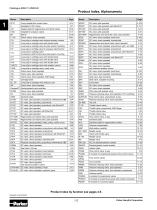
Product Index, Alphanumeric Page 2-way variable flow control valve DC valve, pilot operated DC valve, pilot operated, with EtherCAT Adaptor plate for regenerative and hybrid valves DC valve, pilot operated Subplate for pressure valves DC valve, pilot operated Regenerative and hybrid DC valve, pilot operated Check valves, direct operated DC valve, direct operated, hand lever 2-way slip-in cartridge valve without auxiliary function DC valve, direct operated, hydraulically 2-way slip-in cartridge valve with stroke limiter Regenerative and hybrid valve, direct operated 2-way slip-in cartridge valve...
Open the catalog to page 2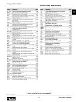
Product Index, Alphanumeric Pressure relief valves, pilot operated, cartridge Pilot valve with pressure relief function Throttle valve, 2-way, proportional, pilot operated High response valve, 2-way Pressure relief valve, direct operated VCD® performance valve, 2-way Pressure reducing valve, pilot operated, pipe mounting Cartridge valve, 2/2-way, active controlled Pressure reducing valve, pilot operated, subplate mounting Throttle valve, 2-way, proportional, pilot operated, with shut-off valve Pressure reducing valve, pilot operated, proportional, pipe mounting High-response valve, 2-way, with...
Open the catalog to page 3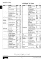
Cover plate Check and throttle valve Axis controller Adaptor plate Body for 2/2-way slip-in cartridge Throttle check valve Throttle valve Unloading valve Pressure relief valve Product Index by Function Cover without auxiliary function C*A C*F Cover for pressure relief function C*G C*B Cover with stroke limiter C*H C*V Cover with shuttle valve C*W Cover for C*C pilot system mounting Slip-in cartridge without cover CE, CP Complete valve, C10C*E with position control Complete valve, TDW directional function, active Check valve C1DB D51* Needle valve, MVI screw-In mounting MV / 9MV Needle valve,...
Open the catalog to page 4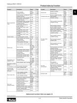
Servo proportional valve Control module Product Index by Function Direct operated, subplate mounting Direct operated, with EtherCAT, subplate mounting Pilot operated, subpl. mounting Pilot operated, with EtherCAT, subplate mounting Pilot operated, subpl. mounting Pilot operated, with EtherCAT, subplate mounting Pilot operated, proportional, 2-way, cartridge Pilot operated, VCD®, 2-way, cartridge Pilot operated, VCD®, 2-way, cartridge with shut-off valve Pilot operated, VCD®, 2-way, cartridge Pilot operated, VCD®, 3-way, cartridge for electrohydraulic controls Direct operated, pipe mounting Shuttle...
Open the catalog to page 5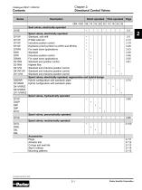
Chapter 2: Directional Control Valves Contents Series Direct operated Pilot operated Seat valves, electrically operated • Spool valves, electrically operated Standard, soft shift • 8 Watt solenoid • Inductive position control • Explosion proof (conform to ATEX and IECEx) • For wash down applications • Standard • Inductive position control • For wash down applications • Standard and position control Highest flow Standard and inductive position control Standard and inductive position control Standard and inductive position control Spool valves, electrically operated, regenerative and hybrid design...
Open the catalog to page 6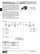
3/2-Way Seated Type Directional Control Valve Series D1SE Characteristics / Ordering Code The directional valve type D1SE is equipped with a wet pin armature solenoid, drain free tapered poppet and compatible with the standards DIN NG06, CETOP 03, and NFPA D03. Due to the 3/2-way design, port A is either connected with P or discharged in the tank. The neutral position (solenoid not activated) is taken automatically by a return spring. This position remains until the solenoid is energized. The valve poppet including activation lever and the armature of the solenoid are located in the pressurized...
Open the catalog to page 7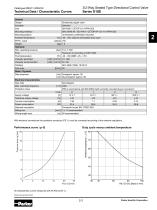
Technical Data / Characteristic Curves General Design Actuation Size Mounting interface Mounting position Ambient temperature MTTFD value Weight Hydraulic Max. operating pressure Fluid Fluid temperature Viscosity permitted Viscosity recommended Filtration Flow max. Static / Dynamic Step response Electrical characteristics Duty ratio Max. switching frequency Protection class Supply voltage Tolerance supply voltage Current consumption Power consumption Solenoid connection Wiring min. Wiring length max. 3/2-Way Seated Type Directional Control Valve Series D1SE Directional poppet valve Solenoid DIN...
Open the catalog to page 8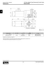
3/2-Way Seated Type Directional Control Valve Series D1SE Subplates and manifolds see chapter 12. The space necessary to remove the plug per EN 175301-803, design type AF is at least 15 mm. The torque for the screw M3 of the plug has to be 0.5 to 0.6 Nm. Parker Hannifin Corporation
Open the catalog to page 9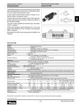
Directional Control Valve Series D1VW The NG06 directional control valve series D1VW provides high functional limits up to 80 l/min in combination with a very low, energy-saving pressure drop. A wide variety of spool options allows to design an unlimited number of hydraulic circuits. Versions with 8 watt coils, position control, ATEX approval, surface protection and connector variants are shown in the following chapters. The valve is also available as sandwich type, see series Z1DW in chapter 7. Valves with explosion proof solenoids Ex e mb ll see series D1VW Explosion Proof in chapter 2 and...
Open the catalog to page 10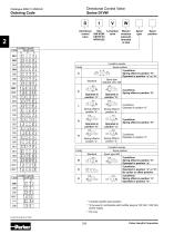
Directional Control Valve Series D1VW Ordering Code Directional Size 3-chamber control DIN NG06 valve valve CETOP 03 NFPA D03 W Wet pin armature solenoid, threaded in tube Spool type Spool position 3 position spools Code Spool type a 0 b 001 002 003 004 005 3 position spools Spool position 3 positions. Spring offset in position “0“. Operated in position “a“ or “b“. Spool type 008,009, 204, 205 2 positions. Spring offset in position “0“. Spring offset in position “b“. Spring offset in position “a“. Spring offset in position “b“. Code Standard 2 position spools Code Spool type a b 020 Spring offset...
Open the catalog to page 11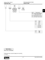
Directional Control Valve Series D1VW Ordering Code Solenoid voltage Solenoid connector as per EN 175301-803, without plug Solenoid option Design series (other connectors are available for D1MW Series) 2 Code Solenoid option omit manual override (standard) T without manual override S2 3) Soft shift orifice size 0.5 mm. S3 3) Soft shift orifice size 0.75 mm. 4N 3) with lockable manual override Further spool types, solenoid voltages and connectors on request. D1VW UK.indd 26.07.2022 Parker Hannifin Corporation
Open the catalog to page 12All Parker Hannifin France SAS catalogs and technical brochures
 MPI™ Medium Pressure Products
20 Pages
 Needle Valves
48 Pages
 Phastite® Tube Connectors
36 Pages
 Quick Coupling Products
230 Pages
 Ball and Plug Valves
72 Pages
 Aluminium Roller Guides
20 Pages
 OSPP-Classic
37 Pages
 Valve Products Isys ISO Series
42 Pages
 2A Pneumatic Cylinders
48 Pages
 Stainless Steel Valves
72 Pages
 Global FRL and P3Y Series
122 Pages
 MMB Hydraulic Cylinders
24 Pages
 PWO Water/oil cooler
12 Pages
 Axial Piston Pumps
28 Pages
 QDC - Quiet DC Cooler
56 Pages
 Air Oil Coolers
18 Pages
 Quick Couplings Catalog
185 Pages
 Crankcase Ventilation
12 Pages
 Condition Monitoring
72 Pages
 Screw-Driven Positioners
111 Pages
 Belt Driven Positioners
151 Pages
 GVI Global Vehicle Inverter
16 Pages
 GVM142 Global Vehicle Motor
16 Pages