- Catalogs
- Parker Hannifin France SAS
- Hydraulic Motors Series V12, V14, V16 Variable Displacement


- Company
- Products
- Catalogs
- News & Trends
- Exhibitions
Hydraulic Motors Series V12, V14, V16 Variable Displacement

Hydraulic Motors Series V12, V14, V16 Variable Displacement
Parker Hannifin's Series V12, V14, and V16 hydraulic motors are bent-axis, variable displacement motors designed for high-performance applications in both open and closed circuit transmissions. The V12 series offers displacements of 60 and 80 cc, the V14 series offers 110 and 160 cc, and the V16 series offers 220 and 270 cc. These motors are capable of handling high speeds and pressures, with features such as low weight pistons, high start-up torque, and a wide displacement ratio.
The V12 series specifications include a maximum intermittent pressure of 480 bar and continuous pressure of 420 bar. The V14 and V16 series have similar pressure ratings, with the V16 series capable of a maximum intermittent pressure of 550 bar and continuous pressure of 500 bar. The motors are designed for high efficiency and low noise levels, with a compact and robust design.
Bearing life is influenced by factors such as system pressure, operating speed, external shaft loads, fluid viscosity, and contamination levels. The B10 value indicates that 90% of bearings will survive at least the calculated number of hours. Parker Hannifin provides bearing life calculations based on specific application details.
The V12 series offers various control options, including pressure compensators (AC and AH), two-position controls (EO and HO), and proportional controls (EP and HP). These controls utilize a setting piston connected to a valve segment, allowing for displacement adjustments between 35° and 6.5°.
These motors are suitable for use in excavators, forestry machines, mining and drilling machines, wheel loaders, mobile winch drives, and more. Optional equipment includes integrated sensors for speed and direction, as well as flushing or pressure relief valves.
Detailed installation dimensions and start-up procedures are provided for each series, ensuring proper setup and operation.
The document describes different control types for the hydraulic motors, including electric, hydraulic proportional, and two-position controls. It explains the operation of these controls, such as the HO control which uses hydraulic signals to move the setting piston between minimum and maximum displacement positions. The threshold pressure for these controls is factory set at 10 bar but can be adjusted between 10-25 bar.
The pressure compensator can override the control settings when system pressure exceeds a certain threshold. The pressure cutoff setting range is 100 – 400 bar, with one revolution corresponding to 48 bar. This feature ensures that the motor displacement is automatically controlled by the system pressure.
The document outlines negative and positive control characteristics. Negative control (M code) keeps the motor at maximum displacement when the solenoid is de-energized, while positive control (T code) keeps it at minimum displacement. The motor displacement is adjusted based on solenoid current or pilot pressure.
A warning is provided regarding the zero-degree capability, which can lead to overspeed and efficiency drops if the motor operates between 0 – 20% displacement.
Details on gauge/pilot ports for various controls are provided, including port sizes and locations for different control types like EPA/EPB, EOA/EOB, HPC, and HOC controls.
The document includes a comprehensive section on ordering codes, detailing the configuration options for motor frame size, function, mounting flange, control signal, and other specifications. It also provides information on optional features like speed sensors and pressure relief valves.
Several charts and figures illustrate the displacement versus control current for different control types, helping to visualize the motor's performance characteristics.
The motors have specific operating temperature limits: main circuit should not exceed 80°C and drain fluid should not exceed 115°C. Continuous high-power operation may require case flushing to maintain fluid viscosity.
Proper inlet pressure is crucial to avoid cavitation, with a minimum of 15 bar recommended. The document provides a table of minimum and maximum case pressures versus shaft speed for different motor sizes.
V12 and V16 motors have two drain ports, while V14 has three. The uppermost drain port should be used to prevent high case pressure, and the drain line should connect directly to the reservoir.
The motors are compatible with petroleum-based fluids, HLP fluids, automatic transmission fluids, and API CD engine oils. Viscosity should be maintained within specified ranges for optimal performance.
The document emphasizes the user's responsibility to ensure proper selection and use of the motors to prevent injury or damage. Users must adhere to industry standards and product guidelines.
References to additional support documents and manuals for installation, start-up, and spare parts are provided.
Catalog excerpts

Visit our homepage for additional support parker.com/pmde Hydraulic Motors Series V12, V14, V16 Variable Displacement
Open the catalog to page 1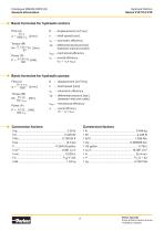
Catalogue MSG30-8223/UK General information Hydraulic Motors Series V12/V14/V16 Basic formulas for hydraulic motors Flow (q) ηv – volumetric efficiency ∆p – differential pressure [bar] (between inlet and outlet) ηhm – mechanical efficiency Basic formulas for hydraulic pumps Flow (q) – volumetric efficiency ∆p – differential pressure [bar] (between inlet and outlet) ηhm – mechanical efficiency Conversion factors Conversion factors
Open the catalog to page 2
Hydraulic Motors Series V12/V14/V16 Parker Hannifin Pump & Motor Division Europe Trollhättan, Sweden
Open the catalog to page 3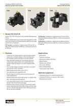
Catalogue MSG30-8223/UK General product information Hydraulic Motors Series V12/V14/V16 Series V12/V14/V16 Series V12/V14/V16 is a bent-axis, variable displacement motor. Parker Variable Bent-axis motors are designed for both open and closed circuit transmissions with focus on high performance machines. V12 series is available in displacement 60 and 80 cc, Max intermittent pressure 480 bar, continuous pressure to 420 bar. V14 series is available in displacement 110 and 160 cc, Max intermittent pressure 480 bar, continuous pressure to 420 bar. V16 series is available in displacement 220 and 270...
Open the catalog to page 4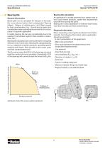
Hydraulic Motors Series V12/V14/V16 Bearing life General information Bearing life can be calculated for that part of the load/ life curve (shown below) that is designated ’Bearing fatigue’. ’Fatigue of rotating parts’ and ’Wear’caused by fluid contamination, etc., should also be taken into consideration when estimating the service life of a motor/ pump in a specific application. In reality, bearing life can vary considerably due to the quality of the hydraulic system (fluid condition, cleanliness, etc.) Bearing life calculations are mainly used when comparing different motor frame sizes. Bearing...
Open the catalog to page 5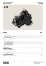
Catalogue MSG30-8223/UK General information Hydraulic Motors Series V12 Parker Hannifin Pump & Motor Division Europe Trollhättan, Sweden
Open the catalog to page 6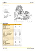
Hydraulic Motors Series V12 V12 cross section 1. End cap 2. Servo control valve 3. Setting piston 4. Valve segment 5. Cylinder barrel 6. Spherical piston with laminated piston ring 7. Synchronizing shaft 8. Heavy-duty roller bearings 9. Bearing housing 10. Output shaft Specifications V12 frame size Displacement [cm3/rev] - max, at 35° - min, at 6.5° Operating pressure [bar] - max intermittent 1) - max continuous Operating speed [rpm] - at 35°, max intermittent 1) - at 35°, max continuous - at 6.5° – 20°, max intermittent 1) - at 6.5° – 20°, max continuous - min continuous Flow [l/min] - max intermittent...
Open the catalog to page 7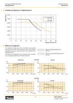
Hydraulic Motors Series V12 Continuous Speed vs. Displacement 8 000 Efficiency diagrams The following diagrams show volumetric and overall efficiencies versus shaft speed at 210 and 420 bar operating pressure, and at full (35°) and reduced (10°) displacements. Information on efficiencies for a specific load condition can be made available from Parker Hannifin. Parker Hannifin Pump & Motor Division Europe Trollhä
Open the catalog to page 8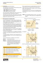
Controls (general information) The following six V12 controls described below satisfy most application requirements: • AC and AH (Pressure compensator) • EO and HO (Two-position controls) • EP and HP (Proportional controls). All controls utilize a setting piston that connects to the valve segment (refer to the picture on page 7). The built-in four-way servo valve acts on the setting piston and determines the displacement which can vary between 35° (max) and 6.5° (min). Hydraulic Motors Series V12 Servo supply pressure is usually obtained from the main high pressure port through the built-in shuttle...
Open the catalog to page 9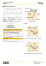
Hydraulic Motors Series V12 AH pressure compensator The AH compensator is similar to the AC (page 9) but incorporates an hydraulic override device. It is utilized in hydrostatic transmissions where a high degree of manoeuvrability at low vehicle speeds is desirable. When the override is pressurized, the servo piston moves to the max displacement position irrespective of system pressure, provided the servo supply pressure is at least 20 bar. The AH compensator is available in two versions: AHI 01 I – Same as the ACI except for the override; internal pilot pressure. AHE 01 I – External pilot pressure...
Open the catalog to page 10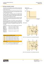
Hydraulic Motors Series V12 EO two-position control The EO is a two-position control, where max and min displacements are governed by a DC solenoid attached to the control cover The EO control is utilized in transmissions where only two operating modes are required: Low speed/high torque or high speed/low torque. The servo piston, normally in the max displacement position, shifts to the min displacement position when the solenoid is activated. Intermediate displacements cannot be obtained with this control. Servo pressure is supplied internally (through the shuttle valve from one of the main...
Open the catalog to page 11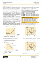
Hydraulic Motors Series V12 EP proportional control The EP electrohydraulic proportional control is used in hydrostatic transmissions requiring a continuously variable shaft speed. The position of the setting piston is governed by a DC solenoid attached to the control cover. When the solenoid current increases above the threshold current, the servo piston starts to move from the max towards the min displacement position. The displacement vs. solenoid current is shown in the diagram to the right. Please note, that the shaft speed vs. current is non-linear; refer to the diagram below. Solenoids...
Open the catalog to page 12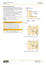
Hydraulic Motors Series V12 HO two-position control The two-position HO control is similar to the EO (page 11) but the pilot signal is hydraulic. The position of the setting piston is governed by the built-in servo valve (same on all compensators and controls). When the applied pilot pressure (port X5) exceeds the pre-set threshold pressure, the setting piston moves from the max to the min displacement position. The threshold pressure is factory set at 10 bar but can be adjusted between 5 and 25 bar. Displacement (setting piston position) Max Max Max The HO two-position control is available in...
Open the catalog to page 13All Parker Hannifin France SAS catalogs and technical brochures
 MPI™ Medium Pressure Products
20 Pages
 Needle Valves
48 Pages
 Phastite® Tube Connectors
36 Pages
 Quick Coupling Products
230 Pages
 Ball and Plug Valves
72 Pages
 Aluminium Roller Guides
20 Pages
 OSPP-Classic
37 Pages
 Valve Products Isys ISO Series
42 Pages
 2A Pneumatic Cylinders
48 Pages
 Stainless Steel Valves
72 Pages
 Global FRL and P3Y Series
122 Pages
 MMB Hydraulic Cylinders
24 Pages
 PWO Water/oil cooler
12 Pages
 Axial Piston Pumps
28 Pages
 QDC - Quiet DC Cooler
56 Pages
 Air Oil Coolers
18 Pages
 Hydraulic Valves Industrial Standard
817 Pages
 Quick Couplings Catalog
185 Pages
 Crankcase Ventilation
12 Pages
 Condition Monitoring
72 Pages
 Screw-Driven Positioners
111 Pages
 Belt Driven Positioners
151 Pages
 GVI Global Vehicle Inverter
16 Pages
 GVM142 Global Vehicle Motor
16 Pages