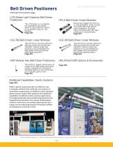
Overview: Belt-driven positioners are crucial for high-speed industrial automation, suitable for applications such as palletizing, machine loading, and automated assembly. Parker offers a range of customizable belt-driven positioners to meet diverse automation needs.
Parker Belt Driven Industrial Systems: Parker's belt-driven actuators are categorized by guidance technology, frame size, and loading properties. They can be pre-configured with Parker motors and gearheads or standard industry mounts.
Product Series:- OSPE..BHD Series: Compact design for high-speed, long-travel, heavy-duty applications.
- HMR High Moment Rodless Series: High payload capacity in a low-profile design, ideal for long travel and high-speed positioning.
- OSPE..B Series: Suitable for precise point-to-point applications with easy installation and low maintenance.
- OSPE..BV Series: Vertical fixed belt-driven actuator for lifting loads vertically.
Additional Capabilities: Parker's gantry systems offer cost-effective solutions for most automation requirements, with custom-tailored options for unique applications.
HPLA and HLE Series: These series provide high-speed, high-acceleration, and long-travel capabilities with robust construction, suitable for single or multi-axis gantries.
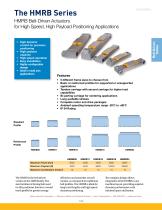
HMRB Series Features:- High dynamic control and payload capacity.
- Configurable design with multiple frame sizes and profiles.
- IP54 rating for harsh environments.
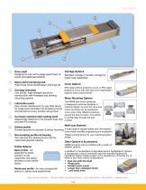
- Options for tandem carriage, bi-parting carriage, and various motor mounting positions.
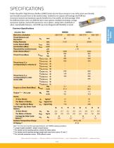
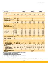
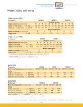
Specifications: Detailed specifications include actuator sizes, belt drive orientations, travel distances, linear speeds, thrust forces, and torque values. The HMRB series offers a range of options for different applications, with specifications for weight, mass, and loading conditions.
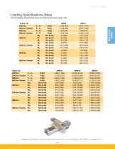
Loading Conditions: Loading conditions are application-dependent, requiring the determination of the center of gravity for the mass/payload attached to the carriage. The document emphasizes that the sum of all loading should not exceed "1" according to the provided formula. It also details the maximum admissible loads and supporting distances for different actuator sizes.
Dimensions: The document provides comprehensive dimensional data for HMRB actuators, including internal lever arm dimensions and maximum permissible unsupported lengths. It distinguishes between "Basic" and "Reinforced" profiles, advising on their application based on support requirements.
Options & Accessories: Various gearhead mounting kit options are available for different actuator sizes, with detailed dimensions and order codes provided. The document includes information on mounted gearhead with motor mounting kit options, specifying dimensions and configurations for different actuator sizes.
Key Recommendations: Ensure actuators are mounted on a solid base to prevent deflection. Use the appropriate deflection graph to ensure application loads do not exceed recommended limits. For optimal performance, select the correct actuator size and configuration based on application-specific loading conditions and dimensions.
Shock Absorbing Bumper: HMR actuators are equipped with impact protection bumpers to absorb energy from unintentional impacts, providing mechanical damage protection. Each carriage has four bumpers, two on each side. Shock absorbers vary by product size, with energy absorption ranging from 3.0 Nm/stroke for smaller sizes to 8.5 Nm/stroke for larger sizes.
Dowel Sleeves: Used for pinning functionality between the carriage and payload, dowel sleeves come in different sizes (7mm, 9mm, 12mm) and are available in packs of 4 or 10, depending on the frame size.
Actuator Mounting: The document provides detailed dimensions for toe-clamp and T-nut mounting options, including holding force specifications per mounting set. The mounting options are designed to accommodate various actuator sizes, ensuring secure installation.
Ordering Information: The ordering process involves selecting from various options such as frame size, actuator design, motor mounting position, carriage design, order stroke, sensor types, and gearhead options. Each selection is coded to create a complete order number for the HMR belt-driven model.
Features of OSPE..BHD Actuators: These actuators are designed for high-speed, long-travel, and heavy-duty applications. They feature integrated ball bearing or roller guides, high thrust and payload capacities, and are suitable for multi-axis applications. The design allows for easy integration into machine layouts.
Specifications: Detailed specifications are provided for various actuator sizes, including maximum travel, payload, acceleration, thrust force, and torque. The document also includes information on load factors and provides examples for calculating load requirements.
Specifications Overview: The document provides detailed specifications for various actuator models, including OSPE25B, OSPE32B, and OSPE50B. Key parameters such as torque, weight, and load capacities are outlined for each model. The document also includes part numbers and maximum order stroke lengths.
Performance and Load Capacities: Each actuator model is described with its maximum load capacities in terms of normal and moment loads. The document specifies the maximum permissible unsupported lengths and provides guidelines for determining end cap and profile mounting placements to minimize deflection.
Mounting and Installation Guidelines: The document emphasizes the importance of proper mounting to prevent excessive deflection. It provides a step-by-step example for calculating load factors and determining the correct placement of mounts. Recommendations for reducing deflection by adjusting the distance between mounts are also included.
Dimensions and Design Considerations: Detailed dimensional drawings are provided for each actuator model, including standard, tandem, and bi-parting carriage configurations. The document specifies the minimum and recommended distances between carriages for optimal performance.
Options and Accessories: The document lists various options and accessories available for the actuators, such as clevis and inversion mounting options. It also includes motor mounting kit options with detailed dimensions and part numbers.
Graphical Data: The document contains graphs illustrating load-distance relationships for different carriage orientations and actuator models. These graphs are essential for ensuring that the application load does not exceed the maximum allowed deflection.
Conclusion: The document serves as a comprehensive guide for selecting and installing Parker Hannifin actuators, providing essential specifications, performance data, and installation guidelines to ensure optimal performance and longevity.
Actuator Specifications: The document provides detailed specifications for various actuator sizes, including OSPE25B, OSPE32B, and OSPE50B. Each actuator size is associated with specific order codes and dimensions, such as bolt circle diameter, screw size, square dimension, pilot diameter, and more. These specifications are crucial for selecting the appropriate actuator for specific applications.
Mounted Motor Options: The document outlines options for mounted motors, detailing the order codes and dimensions for each motor type. It includes descriptions of motor types like LV233-01-10 and BE233FJ-KPSN, along with their respective dimensions such as length coupling housing (LCH), length motor (LM), and motor flange (MF).
Gearhead Mounting Kit Options: This section provides information on gearhead mounting kits, including order codes and dimensions. Key parameters include bolt circle diameter, input drive shaft diameter, and length coupling housing. The document specifies the components included in the kits, such as coupling housing and flange.
Mounted Gearhead with Motor Mounting Kit Options: Details are provided for mounted gearhead and motor options, including order codes and dimensions. The document specifies the components included, such as coupling housing, flange, and gearhead with coupler.
End Cap and Profile Mounting Options: The document describes various end cap types (A1, A2, A3, B1, B4, C1, C2, C3, C4) and their dimensions. It also covers profile mounting options, detailing types with internal threads and thru holes, along with their respective dimensions.
Ordering Information: The document provides a comprehensive guide for ordering actuators, including series, actuator bore size, drive train, carriage type, drive shaft and motor input, mounted gearhead options, and gearhead/motor mounting options. It also specifies the maximum catalog stroke for each actuator size and notes that longer strokes are available upon request.
Ordering Information: The document provides detailed instructions for ordering the OSPE..B model, including a step-by-step guide to selecting order codes from various fields. It highlights the availability of rapid shipment options and offers support through Parker's Virtual Engineer tool.
Features: The OSPE..BV series is designed for vertical applications with a fixed belt-driven actuator and integrated ball bearing guide. Key features include high acceleration and speed, low maintenance, and easy installation. The design supports smaller motors while maintaining robustness.
Specifications: The document outlines performance data for the OSPE20BV and OSPE25BV models, including maximum travel, payload, acceleration, and thrust force. It also details torque specifications, load capacities, and environmental ratings.
Dimensions: Detailed dimensions for the OSPE..BV series are provided, including actuator size, magnetic switch dimensions, and safety distance recommendations. The document emphasizes the importance of incorporating safety distances in design.
Options and Accessories: Various drive shaft options, actuator head orientations, and magnetic switch sets are available. The document also mentions the availability of multi-axis systems and customization options for specific application needs.
LCR Series Features: The LCR Series offers a miniature belt-driven design with versatility for light payload automation. It features a compact footprint, multiple motor mount options, and is suitable for life science applications. The series is pre-engineered for ease of use and quick market deployment.
Overview: The document provides detailed information about Parker Hannifin Corporation's LCR series actuators, which are designed for laboratory automation, micro titer automation, MALDI plate automation, liquid handling, and syringe pumps. These actuators are ideal for high-volume, light-capacity, electrically-controlled motion applications.
General-Purpose Applications: The LCR series is suitable for point-of-purchase kiosks, adjustable guide widths for conveyor lines, storage and retrieval, part shuttling, and light payload automation. It is particularly effective for converting rodless pneumatics to electric systems and general automation for payloads ≤25 lb with basic repeatability requirements.
Compliance and Customization: All LCR series actuators comply with RoHS and CE directives. Parker offers customization options, including blue anodizing and custom carriage designs for larger payloads.
Features: The LCR series includes metric and imperial graduated scales, high rigidity profile sizes, stepper drive options, rugged internal square rails, flexible drive train options, quick mounting options, and various motor mounting options. Encoder options are available for position verification and maintenance.
P2™ Stepper Drive: The P2 drive is a compact, powerful solution for stepper motors, offering full, half, quarter, and sixteenth step modes. It simplifies procurement and installation, providing a robust, high-quality product with no programming required.
Specifications: The document details performance specifications for the LCR30 model, including bidirectional repeatability, duty cycle, maximum acceleration, linear speed, normal load, moment load, axial load, and more. It also provides performance data for different travel lengths and load conditions.
Options and Accessories: The document lists various options and accessories, including encoders, limit sensors, toe clamps, and motor mounts. It provides part numbers and specifications for each accessory.
Ordering Information: The document outlines the ordering process for LCR series actuators, specifying options for series, size, drive train, travel length, bearing type, environmental protection, motor mount position, motor, motor encoder option, home and end-of-travel sensors, and stepper drive/amplifier.
Ordering Information: The document provides detailed ordering information for the P2 Stepper Drive/Amplifier, including various cable sets and mounting kits. Customers can choose from different cable lengths and configurations, such as flying leads or connections to ACR and 6K systems. For longer cable needs, the A1 option is recommended, with cables ordered separately.
Features of Belt Driven Tables: The document outlines the features of the HPLA Series Belt Driven Linear Modules, highlighting their strong construction, high load capacity, and suitability for heavy-duty applications. The modules offer high speed, acceleration, and long travel distances, making them ideal for single-axis products or components in multi-axis gantries.
Specifications: Detailed specifications are provided for various HPLA models (HPLA80, HPLA120, HPLA180), including unit weight, carriage weight, travel and speed capabilities, geometric data, and pulley data. The document emphasizes the importance of considering speed-dependent forces and moments when determining load-bearing capacities.
Applications: The HPLA modules are suitable for a wide range of applications, including materials handling, warehouse technology, machine tool automation, textile machinery building, and process engineering. The document also mentions the availability of Virtual Engineer software for precise carriage loading determination.
Deflection Curves and Specifications: The document provides deflection curves for HPLA profiles, illustrating deflection based on the profile being simply supported at both ends. It considers self-deflection due to the profile's weight and the load to be transported. Exceeding maximum deflection requires additional supports or a larger profile size. Key parameters include Force (N), Unsupported length (mm), and Deflection (mm).
Dual Axis Considerations: For HPLA dual-axis systems, a link shaft bearing is necessary if the critical speed is exceeded. The span between parallel linear modules determines the shaft connection type. Specifications for span distances are provided for different series (HPLA080, HPLA120, HPLA180).
Dimensions: Detailed dimensions for various components, including standard and extended carriages, are provided. The document includes measurements with and without strip seals for different HPLA drive units.
Ordering Information: The document outlines a comprehensive ordering code system for HPLA series, including options for drive systems, bearing options, travel specifications, carriage types, link shaft options, drive shaft configurations, drive housing flanges, gearbox options, motor kits, environmental options, mounting orientations, limit/home switch options, and linear encoders.
Features of Belt-Drive Actuators: HLE-RB series belt-driven linear modules are highlighted for high thrust and long stroke applications. They feature minimal maintenance, integrated T-slots for mounting, and a zero backlash steel reinforced timing belt. The modules offer high load capacities, positional repeatability, and are suitable for clean room environments.
Optional Features: Includes direct mounting for gear reducers, adjustable limit switches, clean room preparation, cable carrier systems, and structural components for multi-axis mounting.
Specifications: Specifications for HLE-RB series include unit weight, carriage weight, and moment of inertia for standard and extended carriages across different models (HLE60-RB, HLE100-RB, HLE150-RB).
Specifications Overview: The document provides detailed specifications for the HLE-RB series, focusing on travel and speed, geometric data, pulley data, torques, forces, and load-bearing capacities. It includes maximum speed, acceleration, and travel distances for standard and extended carriages, along with geometric properties like cross-section and moments of inertia.
Travel and Speed: Maximum speed is 5 m/s with acceleration up to 10 m/s². Travel distances vary with carriage type: 4.0 m for standard and up to 7.9 m for extended carriages.
Geometric Data: Cross-section dimensions and moments of inertia are provided, with a moment of elasticity of 0.72 x 10⁵ N/mm².
Pulley Data and Forces: Details include travel distance per revolution, pulley diameter, and maximum drive torque. Repeatability is noted as ±0.2 mm.
Load-Bearing Capacities: The document outlines the load-bearing capacities for different HLE-RB series models, including transferable thrust force and maximum permissible moment loads. Values are doubled for extended carriages.
Deflection Characteristics: Deflection curves are provided to determine deflection based on profile length and load weight. Recommendations for additional supports or larger profiles are given if maximum deflection is exceeded.
Dual Unit Axis Considerations: Guidance on using link shaft bearings for dual-axis configurations is provided, with critical speed considerations and shaft connection types based on span distance.
Dimensions: Detailed dimensions for various components, including drive and idler options, are provided for the HLE60-RB, HLE100-RB, and HLE150-RB models.
Applications: The HPLA is suitable for materials handling, warehouse technology, machine tool automation, textile machinery, construction, process engineering, testing technology, and cleanroom technology.
Additional Information: For deviations from standard specifications, such as greater speeds or splicing for longer travel distances, consultation with Parker engineering is recommended. The document also mentions the availability of Virtual Engineer software for precise carriage loading determination.
Ordering Information: The document provides a detailed guide for creating a model order code for belt-driven tables. It includes options for series, bearing type, carriage type, unit type, travel length, drive shaft options, shaft configuration, drive station interface, gearbox options, mounting orientation, motor kit options, strip seal options, and limit/home switch options. Each section offers specific codes and descriptions to customize the product according to user needs.
Features: The belt-driven actuators are designed for high thrust and long stroke applications. The HLE-SR series features easily accessible lubrication points, minimal maintenance, integrated T-slots for mounting, and replaceable timing belts. The SR bearing system uses square rail bearings for greater load capacity without increasing size. The document highlights the advantages of low friction, low wear, quiet operation, high efficiency, and long service life.
Drive Principle: The HLE-SR employs a high-performance belt and pulley drive mechanism with a zero backlash steel reinforced timing belt. It supports high speeds, acceleration, and bidirectional repeatability. The drive station can accommodate planetary gear reducers and various motors.
Specifications: Detailed specifications are provided for different models (HLE60-SR, HLE100-SR), including unit weight, carriage weight, moment of inertia, travel and speed, geometric data, pulley data, torques, and forces. The document notes that deviations from standard specifications may be possible with engineering consultation.
Applications: The HPLA series is suitable for materials handling, warehouse technology, machine tool automation, textile machinery, construction, process engineering, testing technology, and cleanroom technology. It is highlighted as a cost-effective solution for advanced machine and handling system construction.
Overview: The document provides detailed specifications and configurations for the HZR series, a rugged vertical axis unit designed for high-speed automation in gantry robot systems. It highlights the mechanical demands and capabilities of the HZR series, focusing on its use in lifting and transporting heavy or bulky loads.
Specifications: The HZR series includes models HZR50, HZR80, and HZR100, each with specific characteristics such as unit weight, moment of inertia, travel and speed capabilities, geometric data, and pulley data. The document provides detailed tables outlining these specifications, including maximum travel, payload, acceleration, and speed for each model.
Force and Moment Loads: The document explains how the forces and moments that the carriage can transfer are speed-dependent. It includes graphs showing the maximum load-bearing capacity of a carriage in one direction of force or torque, with adjustments for extended guiding.
Ordering Information: A comprehensive guide is provided for creating a complete model order code, detailing options for series, table travel, mounting flange, drive station interface, orientation, gearbox, motor kit, limit switch assembly, and extended options.
Gantry Robot Systems: The document describes various gantry robot systems, including their components such as travel limit sensors, gear reducers, vertical drive modules, structural frames, and servo motor systems. It outlines seven standard system configurations designed to meet a wide range of gantry robot applications, emphasizing ease of integration and cost-effectiveness.
Additional Capabilities: Parker offers additional capabilities for their gantry systems, including motors, drives, controls, extended travels, rotary motion modules, cleanroom preparations, external position feedback, vertical axis brakes, end effectors, protective guarding, and custom support structures.
Overview: The document provides detailed specifications and configurations for Parker Hannifin's gantry robot systems, focusing on various systems and their components, capabilities, and accessories.
System Configurations:- System Three: Offers two axes of motion in a vertical plane using a ballscrew-driven ET Cylinder for high thrust in the vertical direction. It includes components like support structures, X-axis drive rail assembly, and Z-axis drive motor.
- System Four: A variation of System Three, suitable for front loading applications, often used as a wall mount unit.
- System Five: Utilizes the HZR belt-driven unit for the vertical axis, allowing higher vertical speed and greater X-axis acceleration.
- System Six: A three-axis system using HPLA/HLE linear modules for X and Y directions and an ET cylinder for the Z-axis, suitable for transporting moderate to heavy loads.
- System Seven: Similar to System Six but with the HZR unit for the vertical axis, providing longer vertical travel and higher speed.
Specifications: Each system's specifications include load capacity, travel distance, and velocity for X, Y, and Z axes. These parameters are interdependent and can be adjusted based on application requirements.
Support Structures: Parker offers both aluminum and steel support structures, with aluminum being lightweight and modular, and steel providing high stiffness for heavy-duty applications.
Options & Accessories:- Limit and Home Sensors: Ensure safe operation by restricting travel within allowable parameters. Available in mechanical or electrical proximity switches.
- Cable Carriers: Essential for transporting cables, designed to match linear actuators and application requirements, using high-flex cables for durability.
- Toe Clamps and Splice Plates: Used for fastening actuators and extending travel beyond standard ranges.
Recommendations: For specific application requirements, consultation with Parker's factory or application engineers is advised to ensure optimal configuration and performance.
T-Nuts and T-Bolts T-nuts and bolts are essential components used to fasten elements into the T-slots of profiles and the upper side of flange plates. The document provides a detailed list of standard and corrosion-resistant part numbers, dimensions, and compatible models for both T-bolts and T-nuts. Key dimensions include measurements such as A, B, C, D, and E, which are crucial for ensuring compatibility with specific models like HPLA080, HLE100-RB, and others.
External Bumpers External bumpers function as adjustable hard stops, fitted into the grooves of the housing profile to restrict total travel. The document lists part numbers, dimensions, and compatible models for external bumpers, highlighting their role in limiting movement in systems like the HPLA and HLE series. Dimensions provided include A, B, C, D, E, F, G, H, and J, which are necessary for proper installation and functionality.


 MPI™ Medium Pressure Products
 Needle Valves
 Phastite® Tube Connectors
 Quick Coupling Products
 Ball and Plug Valves
 Aluminium Roller Guides
 OSPP-Classic
 Valve Products Isys ISO Series
 2A Pneumatic Cylinders
 Stainless Steel Valves
 Global FRL and P3Y Series
 MMB Hydraulic Cylinders
 PWO Water/oil cooler
 Axial Piston Pumps
 QDC - Quiet DC Cooler
 Air Oil Coolers
 Hydraulic Valves Industrial Standard
 Quick Couplings Catalog
 Crankcase Ventilation
 Condition Monitoring
 Screw-Driven Positioners
 GVI Global Vehicle Inverter
 GVM142 Global Vehicle Motor