 Website:
Parker Hannifin France SAS
Group: Parker
Catalog excerpts
3L Tie-Rod Cylinders NFPA Hydraulic Cylinders for working pressures up to 70 bar Parker Hannifin plc Cylinder Division Europe
Open the catalog to page 1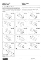
Mounting Styles 3L Cylinder Mounting Styles The standard range of Parker 3L cylinders comprises 15 mounting styles, to suit the majority of applications. General guidance for the selection of the cylinders is given below, with dimensional information about each mounting style shown on pages 10 - 21 for 25.4mm to 152.4mm (1” to 6”) bore sizes, and pages 22 - 29 for 203.2mm (8”) bore sizes. Application-specific mounting information is shown on pages 34 - 35. Where a non-standard mounting style is required to satisfy a particular application, our design engineers will be happy to assist....
Open the catalog to page 2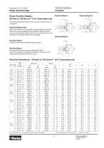
Piston Rod End Details 25.4mm to 152.4mm (1 to 6) bore sizes only Piston Rod End Data for 203.2mm (8”) bore size cylinders is shown on page 46. Style 4 rod ends are recommended for all applications in which the work piece is secured against the rod shoulder. Where the work piece is not shouldered, Style 8 rod ends are recommended. If a rod end style is not specified, Style 4 will be supplied. For applications where a female thread is required. Non-standard piston rod ends are designated 'Style 3'. A dimensional sketch or description should accompany the order. Please specify dimensions KK...
Open the catalog to page 3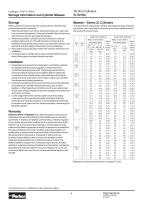
Storage Information and Cylinder Masses Masses Series 3L Cylinders When cylinders must be stored for a period of time, the following procedures are recommended: 1. Store the cylinders in an indoor area which has a dry, clean and non-corrosive atmosphere. Take care to protect the cylinder from both internal corrosion and external damage. 2. Whenever possible, cylinders should be stored in a vertical position (piston rod up). This will minimize corrosion due to possible condensation which could occur inside the cylinder, and seal set due to the weight of the piston and rod assembly. 3. Port...
Open the catalog to page 4
Introduction Contents Piston Rod End Data – 25.4mm to 152.4mm (1” to 6”) bore sizes Storage Information and Cylinder Mass Data Warranty Introduction Standard Specifications Design Features and Benefits Cylinder Selection Check List Mounting Styles Double Rod Cylinders Accessories Mounting Information Push and Pull Forces Piston Rod Sizes and Stop Tubes Stroke Factors and Long Stroke Cylinders Cushioning Pressure Limitations Ports, Locations and Piston Speeds Seals and Fluids Optional Features Replacement Parts and Service Repairs Piston Rod End Data – 203.2mm (8”) bore sizes How to Order...
Open the catalog to page 5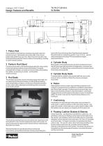
Design Features and Benefits 3 service life of up to five times that of traditional seal materials. Standard seals are suitable for speeds of up to 0.5m/s – special seal combinations including PTFE are available for higher speed applications. Gland seal life is maximised by manufacturing piston rods from precision ground, high tensile carbon alloy steel, hard chrome plated and polished to 0.2µm max. Piston rods are induction case hardened to Rockwell C54 minimum before chrome plating, resulting in a dent-resistant surface. Strict quality control standards and precision manufacture ensure...
Open the catalog to page 6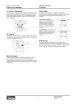
Features and Benefits 9 Cushion Adjustment Piston Seals Needle valves are provided at both ends of the cylinder for precise cushion adjustment, and retained within the head and cap so that they cannot be inadvertently removed. The cartridge type needle valve illustrated below is fitted to cylinders of up to 63.5mm (21/2”) bore – see page 41. A variety of piston seal options is available, to suit different applications. The seal option should be specified at the time of order as a seal type cannot be changed unless the piston is also changed. Cast Iron Piston Rings are extremely durable but...
Open the catalog to page 7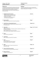
Cylinder Selection Check List The following check list indicates the principal factors which should be considered when selecting a hydraulic cylinder for a particular application. Further information is available on the pages shown. If more detailed information is required about any aspect of a cylinder’s specification, please contact our design engineers who will be happy to assist. The European cylinder inPHorm program can assist with the selection and specification of an hydraulic cylinder for a particular application. Please ask for HY07-1260/Eur. Establish System Parameters – Weight to...
Open the catalog to page 8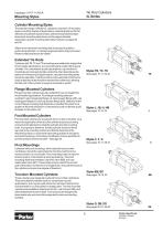
Mounting Styles Cylinder Mounting Styles The standard range of Parker 3L cylinders comprises 15 mounting styles, to suit the majority of applications. General guidance for the selection of cylinders is given below, with dimensional information about each mounting style shown on the pages indicated. Application-specific mounting information is shown on pages 34 and 35. Where a non-standard mounting style is required to satisfy a particular application, our design engineers will be happy to assist. Please contact the factory for details. Extended Tie Rods Cylinders with TB, TC and TD...
Open the catalog to page 9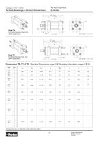
Tie Rods Extended Head End (NFPA Style MX3) ZB + stroke ZJ + stroke P + stroke Tie Rods Extended Cap End (NFPA Style MX2) Dimensions TB, TC & TD See also Dimensions, page 3 & Mounting Information, pages 9 & 34 Bore Ø All dimensions are in millimetres unless otherwise stated. Parker Hannifin plc Cylinder Division Europe
Open the catalog to page 10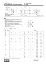
ZB + stroke ZJ + stroke P + stroke Tie Rods Extended Both Ends (NFPA Style MX1) All cylinders are subject to maximum pressure ratings – see page 40. All tie rod threads (dimension DD) are UNF, with the exception of 25.4mm (1”) bore which is UNC. Mounting nuts should be tightened to the torque values shown for tie rod nuts – see page 35. For Styles TB and TC an additional set of mounting nuts are supplied. For Style TD, two additional sets of mounting nuts are supplied. The extra height ‘H’ of the port face applies to the head end of the bore and rod sizes shown in the table below and to the...
Open the catalog to page 11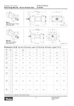
Head Flange Mounts 25.4 to 152.4mm bore Head Rectangular Flange (NFPA Style MF1) Head Square Flange (NFPA Style MF5) Dimensions J & JB See also Dimensions, page 3 & Mounting Information, pages 9 & 34 Bore Ø All dimensions are in millimetres unless otherwise stated. Parker Hannifin plc Cylinder Division Europe
Open the catalog to page 12All Parker Hannifin France SAS catalogs and technical brochures
-
MPI™ Medium Pressure Products
20 Pages
-
Needle Valves
48 Pages
-
Phastite® Tube Connectors
36 Pages
-
Quick Coupling Products
230 Pages
-
Ball and Plug Valves
72 Pages
-
Aluminium Roller Guides
20 Pages
-
OSPP-Classic
37 Pages
-
Valve Products Isys ISO Series
42 Pages
-
2A Pneumatic Cylinders
48 Pages
-
Stainless Steel Valves
72 Pages
-
Global FRL and P3Y Series
122 Pages
-
MMB Hydraulic Cylinders
24 Pages
-
PWO Water/oil cooler
12 Pages
-
Axial Piston Pumps
28 Pages
-
QDC - Quiet DC Cooler
56 Pages
-
Air Oil Coolers
18 Pages
-
Hydraulic Valves Industrial Standard
817 Pages
-
Quick Couplings Catalog
185 Pages
-
Crankcase Ventilation
12 Pages
-
Condition Monitoring
72 Pages
-
Screw-Driven Positioners
111 Pages
-
Belt Driven Positioners
151 Pages
-
GVI Global Vehicle Inverter
16 Pages
-
GVM142 Global Vehicle Motor
16 Pages


