- Catalogs
- Parker Electromechanical and Drives Division Europ
- Torque Motors – Kit version
Torque Motors – Kit version
1 /111Pages

Torque Motors – Kit version
1 /111Pages
Catalog excerpts

Torque Motors – Kit version TK Series Technical Manual PVD3645
Open the catalog to page 1
Parker Hannifin Manufacturing France SAS Electromechanical & Drives Division Europe Etablissement de Longvic 4 Boulevard Eiffel - CS40090 21604 LONGVIC Cedex - France manufacturer, with brand name Parker, declare under our sole responsibility that the products SERVOMOTORS TYPE TK satisfy the arrangements of the directives : Directive 2014/35/EU : “Low Voltage Directive”, LVD Directive 2011/65/EU : “Restriction of Hazardous Substances”, RoHS Directive 2014/30/EU : “Electromagnetic Compatibility”, EMC and meet standards or normative document according to : EN 60034-1:2010/AC:2010 : Rotating electrical...
Open the catalog to page 2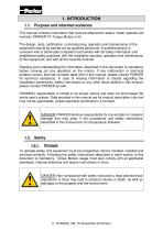
1. INTRODUCTION 1.1. Purpose and intended audience This manual contains information that must be observed to select, install, operate and maintain PARKER TK Torque Motors in kit. The design, tests, certification, commissioning, operation and maintenance of the equipment should be carried out by qualified personnel. A qualified person is someone who is technically competent and familiar with all safety information and established safety practices; with the installation process, operation and maintenance of this equipment; and with all the hazards involved. Reading and understanding the information...
Open the catalog to page 5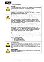
General Safety Rules Generality DANGER: The installation, commission and operation must be performed by qualified personnel, in conjunction with this documentation. The qualified personnel must know the safety (C18510 authorization, standard VDE 0105 or IEC 0364) and local regulations. They must be authorized to install, commission and operate in accordance with established practices and standards. Electrical hazard Servo drives may contain non-insulated live AC or DC components. Respect the drives commissioning manual. Users are advised to guard against access to live parts before installing...
Open the catalog to page 6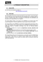
2. PRODUCT DESCRIPTION 2.1. Quick URL All informations and datas are avaible on : http://www.parker.com/eme/tk 2.2. Overview The TK frameless servomotor are the active parts of a servo motor: a rotor and a stator. The TK series can not be used alone and must integrated into a complete system to provide a complete torque motor. The design, the construction, the certification and the tests are the responsibility of the integrator. TK Torque Motors Series in kit version from PARKER are innovative direct drive solutions designed for industrial applications requiring high torque at low speed. TK Torque...
Open the catalog to page 7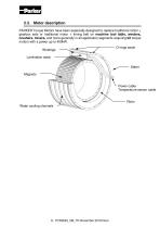
2.3. Motor description PARKER Torque Motors have been especially designed to replace traditional motor + gearbox sets or traditional motor + timing belt on machine tool table, winders, crushers, mixers, and more generally in all application segments requiring kit torque motors with a power up to 400kW. Windings O-rings seals Lamination stack Stator Magnets Power cable Temperature sensor cable Rotor Water cooling channels
Open the catalog to page 8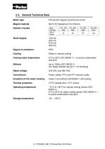
2.4. General Technical Data Motor type Permanent-magnet synchronous motor Magnet material Nd-Fe-B (Neodymium Iron Boron) Size: Polarity: Nbr of poles: Shaft heights Water or natural cooling Cooling water temperature Up to 1000m (IEC 60034-1) (for higher altitude see §3.1.1 for derating) Rated voltage Power cables, PTC and KTY sensors cable Insulation of the stator winding Class F according to EN 60034-1 with potting Thermal protection Operating temperature -15°C to +40°C for natural cooling version (IEC 60034-1) 0°C to 40°C for water cooled version (IEC 60034-1) – to avoid condensation see §3.5...
Open the catalog to page 9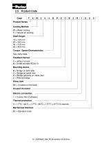
2.5. Product Code Code Product Series Cooling Method W = Water cooling A = Natural air cooling Shaft Height 13 = 130 mm 20 = 200 mm 30 = 315 mm 40 = 400 mm Torque / Speed Characteristics See motor data. Feedback Sensor K = without sensor B = Endat encoder ECN113 Mounting device B = Bridge on both side C = Bridge on cable inlet D = Bridge opposite on cable inlet Z = Without bridge Wires inlet B2 = 2 meters on the back Unused character Electric connection 1 = 3 wires inlet (3 phases) Thermal protection 0 = 1 PTC 140°C + 1 PTC 150°C + 1 KTY (+1KTY in reserve) Mechanical Interface 00 = Standard motor...
Open the catalog to page 10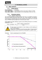
3. TECHNICAL DATAS 3.1. Motor selection 3.1.1. Altitude derating From 0 to1000 m : no derating From 1000 to 4000 m : torque derating of 5% for each step of 1000 m for TKW From 1000 to 4000 m : torque derating of 10% for each step of 1000 m for TKA 3.1.2. Temperature derating 3.1.2.1. Natural cooled motor The maximal temperature for natural cooling is 40°C. But, it is possible to increase a little bit the ambient temperature above 40°C, with a torque reduction. The following formula gives an indicative about the torque derating at low speed. But in any case refer to PARKER technical department...
Open the catalog to page 11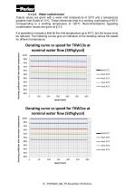
3.1.2.2. Water cooled motor Typical values are given with a water inlet temperature of 25°C and a temperature gradient Inlet-Outlet of 10°C. These references lead to a winding overheating of 95°C corresponding to a winding temperature of 120°C. Recommendations regarding condensation issues are given at § 3.5 It is possible to increase a little bit the Inlet temperature up to 45°C, but the torque must be reduced. The following curves give an indicative of the derating versus the speed for different temperature. Derating coefficient with inlet water temperature Derating curve vs speed for TKW13x...
Open the catalog to page 12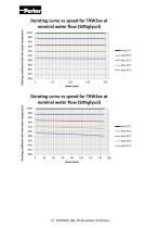
Derating coefficient with inlet water temperature Derating curve vs speed for TKW3xx at nominal water flow (50%glycol) 100% 98% 96% 94% 92% Derating coefficient with inlet water temperature Derating curve vs speed for TKW4xx at nominal water flow (50%glycol) 100% 98% 96% 94% 92%
Open the catalog to page 13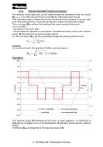
Thermal equivalent torque (rms torque) The selection of the right motor can be made through the calculation of the rms torque Mrms (i.e. root mean squared torque) (sometimes called equivalent torque). This calculation does not take into account the thermal time constant. It can be used only if the overload time is much shorter than the copper thermal time constant. The rms torque Mrms reflects the heating of the motor during its duty cycle. Let us consider: - the period of the cycle T [s], - the successively samples of movements i characterized each ones by the maximal torque Mi [Nm] reached...
Open the catalog to page 14All Parker Electromechanical and Drives Division Europ catalogs and technical brochures
 AC15 Variable Speed Drive
16 Pages
 Belt Driven
32 Pages
 SensoNODETM
2 Pages
 Medical solutions
2 Pages
 RS and AXEM Series
14 Pages
 AC890
AC89025 Pages
 HPLA Linear Actuators
40 Pages
 AC10 Variable Speed Drive
26 Pages
 AC30 Variable Speed Drive
42 Pages
 Parker Automation Controller
20 Pages
 Explosion Proof Servo Motors
44 Pages
 Parker Gearboxes
36 Pages
Archived catalogs
 GVM Global Vehicle Motor
24 Pages
 Frameless Servo Motors
44 Pages
 ETH Electro Cylinder_2019
60 Pages
 GVI Global Vehicle Inverter
16 Pages
 RTS, RS, RX and AXEM Series
24 Pages
 Motion Solutions
16 Pages
 PE Series
12 Pages
 Belt Driven Positioners
151 Pages
 PSD1 Parker Servo Drive
12 Pages
 DC590+ Product Catalog
20 Pages
 PSD1 Parker Servo Drive
16 Pages
 ETHERNET Powerlink
20 Pages
 PTN Planetary Gearbox
4 Pages
 PS / RS Series
16 Pages
 HKW Series
133 Pages
 SMB Motors
28 Pages
 TMW Series Torque Motors
32 Pages
 DC590P
28 Pages
 ETH Electro Cylinder_2012
56 Pages


- Cylinder
- Parker actuator
- Industrial robot
- Parker linear actuator
- Parker electric actuator
- Planetary gearbox
- Coaxial gearhead
- Positioning table
- Precision gearhead
- Translation stage
- Compact gearhead
- Solid-shaft gearhead
- Gear train gear reducer
- Gearbox for industrial applications
- Compact actuator
- Precision positioning table
- Servo-amplifier
- Multi-stage gearhead
- Single-stage gearhead