- Catalogs
- Parker Electromechanical and Drives Division Europ
- ETH Electro Cylinder_2012
ETH Electro Cylinder_2012
1 /56Pages

ETH Electro Cylinder_2012
1 /56Pages
Catalog excerpts
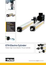
climate control process control sealing & shielding Parker High Force Electric Thrust Cylinder ENGINEERING YOUR SUCCESS.
Open the catalog to page 1
WARNING — USER RESPONSIBILITY FAILURE OR IMPROPER SELECTION OR IMPROPER USE OF THE PRODUCTS DESCRIBED HEREIN OR RELATED ITEMS CAN CAUSE DEATH, PERSONAL INJURY AND PROPERTY DAMAGE. • This document and other information from Parker-Hannifin Corporation, its subsidiaries and authorized distributors provide product or system options for further investigation by users having technical expertise. • The user, through its own analysis and testing, is solely responsible for making the final selection of the system and components and assuring that all performance, endurance, maintenance, safety and warning...
Open the catalog to page 2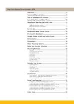
High Force Electro Thrust Cylinder - ETH Overview 5 Technical Characteristics 8 Step by Step Selection Process 9 Calculating Required Axial Force 10 Selection of the Size and Screw Lead 11 Required maximum axial force 11 Required maximum velocity 11 Required maximum acceleration 11 Service life 12 Permissible Axial Thrust Forces 14 Permissible Side Load 15 Stroke, Usable Stroke and Safety Travel 16 Relubrication 17 Dimensions 18 Motor Mounting Options 19 Motor and Gearbox Selection 21 Mounting Methods 22 Standard 22 Center Trunnion Mounting 22 Rear Eye Mounting 23 Rear Clevis 23 Rear Plate 25...
Open the catalog to page 3
Parker Hannifin The global leader in motion and control technologies A world class player on a local stage Global Product Design Parker Hannifin has more than 40 years experience in the design and manufacturing of drives, controls, motors and mechanical products. With dedicated global product development teams, Parker draws on industry-leading technological leadership and experience from engineering teams in Europe, North America and Asia. Local Application Expertise Parker has local engineering resources committed to adapting and applying our current products and technologies to best fit our...
Open the catalog to page 4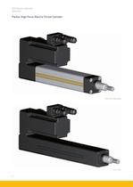
ETH Electric Cylinder Overview Parker High Force Electro Thrust Cylinder ETH IP54 (Standard) ETH IP65 6
Open the catalog to page 6
ETH Electric Cylinder Overview Product Design Ballscrew A high-quality precision class 7 ballscrew in accordance with ISO 3408 is used. The ball bearings between screw and nut ensure a low frictional resistance. This ensures an especially smooth operation over the entire speed range, high service life and excellent efficiency. Screw support bearing (front end) The front screw support bearing is supported by a polymer sliding bearing. This eliminates vibration and run-out. The result is quieter, smoother motion with better precision, longer screw life, and increased dynamic performance. Piston...
Open the catalog to page 7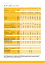
ETH Electric Cylinder Technical Characteristics Technical Characteristics Cylinder size type Unit Screw lead Screw diameter [mm] [mm] M05 5 ETH032 M10 M16 10 16 16 M05 5 ETH050 M10 M20 10 20 20 M05 5 ETH080 M10 M32 10 32 32 Travels, speeds and accelerations [mm] Available strokes 1) Max. permissible speed at stroke = 50-400 mm 600 mm 800 mm 1000 mm 1200 mm 1400 mm 1600 mm Max. Acceleration [mm/s] [mm/s] [mm/s] [mm/s] [mm/s] [mm/s] [mm/s] [m/s2] continuous from 50continuous from 50continuous from 501000 & standard strokes 1200 & standard strokes 1600 & standard strokes 333 286 196 146 4 667 540...
Open the catalog to page 8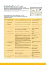
ETH Electric Cylinder Step by Step Selection Process Step by Step Selection Process The following sizing steps help you to find the suitable electro cylinder. Select an electro cylinder using estimated application data. Calculate the actual application data using the sizing steps described below. If your application’s requirements exceed a maximum value, please choose a larger electro cylinder and recheck the maximum values. Perhaps, a smaller electro cylinder can also meet the requirements. Automated dimensioning with the help of the "EL Sizing Tool" A dimensioning tool simplifies the dimensioning...
Open the catalog to page 9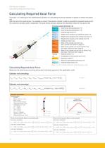
ETH Electro Cylinder Calculating Required Axial Force Calculating Required Axial Force Formulas 1 & 2 below give the mathematical equation for calculating the thrust required to extend or retract the piston rod. With the aid of the axial forces, it is possible to check if the electro cylinder is able to provide the required forces and if the maximum buckling load is respected. The axial forces are also used as the calculation basis for the service life. Formula symbols (Formula 1-2) = Axial forces during extension in N Fx,a,j mKs,Stroke x α Service loading = Selected stroke in m = Maximum permissible...
Open the catalog to page 10
ETH Electro Cylinder Selection of the Size and Screw Lead Selection of the Size and Screw Lead Required maximum axial force Determine the maximum axial force (page 10) that the electro cylinder must provide. Preselection of the electro cylinder Using the calculated force required from page , compare the actual ETH specifications (page 8) to determine which profile size will produce enough force. Once you have determined a profile size, determine that the unit will physically fit in the space allowed by the application (including parallel or in-line motor mounts). Required maximum velocity The...
Open the catalog to page 11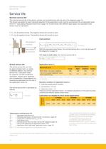
Service life Service life The nominal service life of the electro cylinder can be determined with the aid of the diagrams page 13. The forces calculated for each individual segment of the application cycle must be summarized into an equivalent axial force Fm "Calculating Required Axial Force" (page 10). If axial forces with different signs apply, two equivalent axial forces must be calculated: Fmi for all positive forces. The negative forces will convert to zero. Fm2 for all negative forces. The positive forces will convert to zero. With the equivalent axial forces, the nominal service life L...
Open the catalog to page 12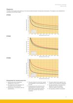
ETH Electro Cylinder Service life Diagrams The given values apply when adhering to the recommended lubrication intervals (see relubrication). The diagrams were established in accordance with DIN ISO 3408‑5 ETH032 2400 2200 Equivalent axial force Fm [N] 2000 1800 1600 1400 1200 1000 800 600 400 200 ETH032, M05 ETH032, M10 ETH032, M16 0 0 2000 4000 6000 8000 10000 12000 14000 16000 18000 20000 Nominal service life L [km] ETH050 4500 Equivalent axial force Fm [N] 4000 3500 3000 2500 2000 1500 1000 500 ETH050, M05 ETH050, M10 ETH050, M20 0 0 2000 4000 6000 8000 10000 12000 14000 16000 18000 20000...
Open the catalog to page 13All Parker Electromechanical and Drives Division Europ catalogs and technical brochures
 AC15 Variable Speed Drive
16 Pages
 Belt Driven
32 Pages
 SensoNODETM
2 Pages
 Medical solutions
2 Pages
 RS and AXEM Series
14 Pages
 AC890
AC89025 Pages
 HPLA Linear Actuators
40 Pages
 AC10 Variable Speed Drive
26 Pages
 AC30 Variable Speed Drive
42 Pages
 Parker Automation Controller
20 Pages
 Explosion Proof Servo Motors
44 Pages
 Parker Gearboxes
36 Pages
Archived catalogs
 GVM Global Vehicle Motor
24 Pages
 Frameless Servo Motors
44 Pages
 ETH Electro Cylinder_2019
60 Pages
 GVI Global Vehicle Inverter
16 Pages
 RTS, RS, RX and AXEM Series
24 Pages
 Motion Solutions
16 Pages
 PE Series
12 Pages
 Belt Driven Positioners
151 Pages
 PSD1 Parker Servo Drive
12 Pages
 DC590+ Product Catalog
20 Pages
 PSD1 Parker Servo Drive
16 Pages
 ETHERNET Powerlink
20 Pages
 PTN Planetary Gearbox
4 Pages
 PS / RS Series
16 Pages
 HKW Series
133 Pages
 SMB Motors
28 Pages
 Torque Motors – Kit version
111 Pages
 TMW Series Torque Motors
32 Pages
 DC590P
28 Pages


- Parker actuator
- Industrial robot
- Parker linear actuator
- Parker electric actuator
- Planetary gearbox
- Coaxial gearhead
- Positioning table
- Precision gearhead
- Translation stage
- Parker servomotor
- Compact gearhead
- Solid-shaft gearhead
- Gear train gear reducer
- Gearbox for industrial applications
- Compact actuator
- Precision positioning table
- Servo-amplifier
- Multi-stage gearhead
- Single-stage gearhead