
- Catalogs
- Parker Electromechanical and Drives Division Europ
- Belt Driven Positioners


Belt Driven Positioners

Belt Driven Positioners
Belt-driven actuators are crucial for high-speed industrial automation, suitable for applications such as palletizing, storage, machine loading, and automated assembly. Parker offers a range of belt-driven positioners with various configurable options, capable of integrating into complete motion systems with motors, drives, controls, and more.
Parker's belt-driven actuators are categorized into series based on guidance technology, frame size, and loading properties. They can be pre-configured with Parker motors and gearheads or standard industry mounting options.
- OSPE..BHD Series: Compact design for high-speed, long-travel, heavy-duty applications.
- HMR High Moment Rodless Series: High payload capacity in a low-profile design, ideal for long travel lengths and high-speed positioning.
- OSPE..B Series: Suitable for precise point-to-point applications with high-speed operation and low maintenance.
- OSPE..BV Series: Vertical fixed belt-driven actuator for lifting loads vertically.
Parker's gantry systems offer cost-effective solutions for automation requirements, with custom-tailored options for unique applications.
- HPLA Belt-Driven Linear Modules: High-speed, high-acceleration modules with rigid construction.
- HLE-RB and HLE-SR Series: Proven performers for long life and trouble-free operation, suitable for single-axis or multi-axis gantries.
- High dynamic control for precision positioning.
- High payload capacity and speed operation.
- Configurable design with multiple frame sizes and profiles.
- IP54 rating for protective covers.
The document provides detailed specifications for various actuator sizes, including travel distance, pulley diameter, linear speed, acceleration, repeatability, thrust force, torque, inertia, unit weight, and ambient temperature range. The HMR series is noted for its user-friendly design and versatility, with options for different drive trains, mounting, and protective covers.
The document provides detailed specifications for Parker Hannifin's HMRB series actuators, focusing on weight, mass, and inertia across different product sizes (HMRB08, HMRB11, HMRB15, HMRB18, HMRB24). It includes data on actuator weight, moving mass carrier, and inertia calculations.
Each actuator version (B, C, R, S) has specific weights for zero-order stroke and per meter order stroke. The moving mass carrier weight varies by carriage version (0, 1). Total mass is calculated using the formula: mtot = m0 + mC + order stroke * mmt.
Inertia values are provided for different motor mounting positions (090°/270°, 000°/180°) and include inertia for zero-order stroke, per meter order stroke, and per kg moving mass. Total inertia is calculated using the formula: Jtot = J0 + order stroke * Jmt + mC * Jkg + m * Jkg.
Loading conditions depend on application-specific external forces and moments. The document emphasizes ensuring the sum of all loads does not exceed '1' using the formula: L = Fy/Fy(max) + Fz/Fz(max) + Mx/Mx(max) + My/My(max) + Mz/Mz(max) ≤ 1.
Actuators must be mounted on a solid base to prevent deflection. The document provides guidelines for maximum permissible unsupported lengths and deflection limits, emphasizing the importance of proper actuator mounting placement.
Dimensions for both 'Basic' and 'Reinforced' profiles are provided, along with detailed tables for actuator and carriage dimensions. The document also includes instructions for calculating overall length (OAL) based on order stroke and safety stroke.
Various gearhead mounting kit options are available, with specifications for bolt circle diameter, screw size, pilot diameter, and input drive shaft dimensions. The document provides order codes for selecting appropriate gearhead and motor mounting kits.
This document serves as a comprehensive guide for selecting and configuring HMRB actuators, providing essential data for engineers to ensure optimal performance and compatibility with specific applications.
The document provides detailed specifications for Parker Hannifin's OSPE Series electric motor-driven actuator systems, which are modular and designed for various applications. Key specifications include actuator sizes (OSPE20BHD, OSPE25BHD, OSPE32BHD, OSPE50BHD), integrated guide rail types (Ball Bearing or Roller Guide), travel distance per revolution, pulley diameter, maximum linear speed, acceleration, repeatability, order stroke, thrust force, torque on drive shaft, and load capacities.
Each actuator size has specific performance parameters such as maximum thrust force, torque, and load capacities. For instance, the OSPE50BHD can handle a maximum thrust force of 3,120 N and a torque of 177 Nm. The document also details the maximum permissible unsupported length and the importance of proper mounting to prevent deflection.
The document emphasizes the need for solid machine base or frame structure mounting using end cap and profile mounts to ensure minimal deflection. It provides guidelines for calculating load factors and determining the correct placement of mounts to maintain structural integrity.
Detailed dimensions for each actuator size are provided, including order stroke requirements, safety distances, and minimum and recommended distances between carriages for optimal performance.
The document lists various options and accessories, including gearhead mounting kits and motor options, with specific order codes for easy selection and ordering. It highlights the availability of rapid shipment for certain configurations.
Graphs are included to illustrate the relationship between thrust force, speed, and stroke, as well as load and deflection characteristics for different actuator configurations.
The document provides detailed specifications and features of Parker Hannifin's OSPE..B Belt-Driven Actuators, designed for point-to-point applications. These actuators are known for their integrated drive and guidance system, tandem carriage for increased load capabilities, and a wide range of accessories and mounting options. They are suitable for harsh environments and offer high-speed, precise, and low-maintenance operation.
- Integrated drive and guidance system with tandem carriage for increased load capabilities.
- Long available strokes and complete motor, gearhead, and control packages.
- Ambient temperature range from -30˚C to +80˚C and IP 54 rating.
- PowerSlide and ProLine options for external bearing installation in various positions.
- Maximum travel distances: OSPE25BHD (3,000 mm), OSPE32BHD (5,000 mm), OSPE50BHD (5,000 mm).
- Maximum payloads: OSPE25BHD (160 N), OSPE32BHD (300 N), OSPE50BHD (850 N).
- Maximum acceleration: 10 m/sec² for all models.
- Repeatability: ±50 µm.
- Thrust force: OSPE25B (50 N), OSPE32B (150 N), OSPE50B (425 N).
- Carriage bearing design configurations include standard carriage, PowerSlide, and ProLine for different load capabilities.
- Optional carriage orientations and actuator mounting options are available for various application needs.
- Load factors must not exceed a combined value of "1" to ensure safe operation.
- Actuators must be mounted on a solid machine base or frame structure to prevent excessive deflection.
- End cap and profile mounts should be positioned appropriately based on load and length requirements.
- Deflection can be minimized by reducing the distance between mounts.
The OSPE..B Series actuators are versatile and robust solutions for linear traverse applications, offering high configurability and ease of integration into various machine layouts. They are designed to meet rigorous environmental and performance criteria, making them ideal for precise point-to-point applications.
The document provides detailed specifications for Parker Hannifin's OSPE..BV belt-driven tables and LCR Series actuators. Key specifications for the OSPE20BV and OSPE25BV models include:
- Travel Distance per Revolution: 108 mm for OSPE20BV and 160 mm for OSPE25BV.
- Maximum Linear Speed: 3 m/s for OSPE20BV and 5 m/s for OSPE25BV.
- Maximum Acceleration: 20 m/s² for both models.
- Repeatability: ±50 µm.
- Maximum Order Stroke: 1,000 mm for OSPE20BV and 1,500 mm for OSPE25BV.
- Maximum Thrust Force: 650 N for OSPE20BV and 1,430 N for OSPE25BV.
- Maximum Torque on Drive Shaft: 12 Nm for OSPE20BV and 38 Nm for OSPE25BV.
- Ambient Temperature Range: -30 to +80°C.
- IP Rating: IP 20.
The document outlines the dimensions for the OSPE..BV models, including actuator sizes, minimum and recommended distances between drive heads, and safety distances for order strokes. It also provides detailed dimensions for various components of the actuators.
The document provides a comprehensive guide for ordering the OSPE..BV models, detailing the series, bore size, drive train, carriage options, order stroke, hardware, gearhead/motor mounting options, magnetic sensor mounting, and drive shaft configuration.
The LCR Series is highlighted for its versatility and ease of use, featuring a miniature footprint, internal square rail or glider bearing design, and a 100% duty cycle. It is designed for light payload automation with selectable travel lengths up to 1000 mm and payloads up to 100 N. The LCR Series is ideal for laboratory automation and other applications requiring high precision and reliability.
The P2 Drive is presented as a compact, OEM-friendly solution that complements the LCR Series. It offers features such as adjustable run and standby current, multiple step modes, and easy installation. The drive is designed to simplify procurement and reduce time to market for new products.
The document outlines the specifications for the LCR30, a compact linear motion system designed for OEM instrument manufacturers. Key features include a width of 30 mm and height of 40 mm, repeatability of ±0.2 mm, and maximum normal and axial loads of 90 N and 45 N, respectively. The system supports a maximum speed of 870 mm/s and a travel length of up to 1000 mm. It includes components such as an amplifier/drive, motor, actuator, bearings, seals, and limit sensors.
The LCR30's performance varies with travel length, with detailed data provided for table weight and total inertia reflected for no load and a 2.5 kg load. The document also includes linear speed-force performance graphs for different configurations, highlighting thrust force capabilities at various speeds.
Detailed dimensions are provided for both the LCR22 and LCR30 models, including motor options and encoder configurations. The document specifies mounting options and dimensions for various motor mounts, including NEMA 17 and NEMA 23 stepper motors.
The document lists available options and accessories, such as encoders, limit sensors, and toe clamps. Encoder specifications include counts per revolution and bore sizes, while limit sensors offer protection with various configurations and cabling options.
A comprehensive ordering guide is provided, detailing the selection process for series, size, drive train, travel length, bearing type, environmental protection, motor mount position, motor type, encoder options, and stepper drive/amplifier configurations.
The HPLA series is highlighted for its robust construction, capable of handling high loads and speeds. It features a steel roller bearing option, thrust force capacity up to 5455 N, and travel lengths up to 9 meters. The system is designed for high-speed, high-acceleration applications, with a focus on durability and precision.
- Modular drive and guide systems for increased stiffness and low maintenance.
- Options for adaptation to different environments, including clean rooms and food industry applications.
- Roller bearing design for smooth linear motion and high load capacity.
- Direct drive options with Parker Stealth series gearheads.
- Extruded aluminum housing for maximum rigidity and minimum weight.
- Available in various models (HPLA080, HPLA120, HPLA180) with different load-bearing capacities and dimensions.
- Maximum speed of 5 m/s and acceleration of 10 m/s².
- Repeatability of ±0.2 mm, with options for improved precision.
- Load-bearing capacity and permissible moment loads are speed-dependent and vary with carriage type (standard or extended).
- Deflection curves are provided to determine deflection based on profile length and load weight.
- Dual axis considerations include the use of link shaft bearings for large center-to-center distances.
The document provides detailed specifications for various components related to the HLE series of belt-driven tables by Parker Hannifin Corporation. It includes data on moment of inertia, travel and speed, geometric data, pulley data, torques, and forces. The specifications are divided into sections for different models such as HLE60-RB, HLE100-RB, and HLE150-RB, each with specific load-bearing capacities and permissible moment loads.
The moment of inertia values are provided for standard and extended carriages, with measurements in kg-cm² and lb-in². These values are crucial for understanding the rotational dynamics of the drive shaft.
The document outlines maximum speed, acceleration, and travel distances for standard and extended carriages. It notes that greater speeds and accelerations may be achievable under certain conditions.
Details on cross-section dimensions, moments of inertia (Ix and Iy), and moment of elasticity are provided, which are essential for structural analysis and design.
Information on travel distance per revolution, pulley diameter, maximum drive torque, and belt traction is included. Repeatability is noted as ±0.2 mm, indicating precision in positioning.
The document provides graphs and data on the load-bearing capacity of carriages and timing belts for different HLE models. It emphasizes that these capacities are speed-dependent and may require derating when multiple loads are applied.
Deflection curves are provided to help determine the deflection based on profile length and application load weight. The document advises on the need for additional supports if maximum deflection is exceeded.
Guidance is given on using link shaft bearings for dual-axis configurations, with specifications on the span between units and critical speed considerations.
The HPLA system is recommended for various applications, including materials handling, warehouse technology, machine tool automation, textile machinery, construction, process engineering, testing technology, and cleanroom technology.
The document highlights features such as T-slots for load attachment, dust protection, and easy belt replacement mechanisms. It also mentions the availability of Virtual Engineer software for precise carriage loading determination.
Parker Hannifin Corporation offers seven standard gantry robot system configurations designed to meet a wide range of applications. These configurations simplify the selection process, reduce lead times, and lower costs. The systems are flexible, allowing for longer travels and increased loads depending on specific parameters.
- System One: Two-axis horizontal motion using HPLA or HLE Linear Modules. Suitable for rapid transport of light to moderate loads.
- System Two: Two-axis system with increased load capacity and longer travel, ideal for moderate to heavy loads.
- System Three: Two-axis vertical motion with high thrust capability, minimizing moment and side loading effects.
- System Four: Variation of System Three, optimized for front loading applications, often wall-mounted.
- System Five: X-Z system with HZR belt-driven unit for higher vertical speed and acceleration.
- System Six: Three-axis system with high vertical thrust capacity, suitable for moderate to heavy loads over long distances.
- System Seven: Three-axis system with HZR unit for superior stiffness and stability, handling moderate to heavy loads.
- Aluminum Structures: Lightweight, economical, and modular, suitable for light to medium duty.
- Steel Support Structures: Heavy-duty, high stiffness, ideal for higher overhead gantries.
Parker's gantry systems are cost-effective and easy to integrate, with additional capabilities for special applications. Options include electromechanical limit switches, proximity limit switches, and load attachment plates.
The document outlines the use of sensors to ensure safe operation by limiting travel within permissible parameters, which depend on load, velocity, and acceleration. A 'Home' sensor can be set for machine start-up, and limit sensors can be positioned to further restrict the operating range. Both mechanical and electrical proximity switches are available.
The document details specifications for 4-wire NPN and PNP switches, including part numbers for various models. Inductive proximity switches are triggered by a tripping plate and offer both NO and NC operations. Key specifications include a sensing distance of 4 mm, voltage supply of 10-30 VDC, and protection class IP67.
Cable carriers are essential for transporting cables to the carriage or payload. The document emphasizes the use of high-flex cables and provides guidelines for cable routing, including avoiding twisting and ensuring even weight distribution.
Toe clamps are used for fastening linear actuators, with dimensions provided for various models. Splice plates allow for extended travel beyond standard extrusion lengths, with specific recommendations for installation.
These components are used to fasten elements into T-slots. The document provides part numbers and dimensions for standard and corrosion-resistant options.
External bumpers serve as adjustable hard stops to restrict travel. Dimensions and part numbers are provided for different series.
Catalog excerpts

Belt Driven Positioners Belt-driven actuators are ideal for high speed, industrial automation applications. These positioners are used in either single or multi-axis configurations such as gantry robots, and are ideal for applications such as palletizing, storage and retrieval, machine loading, parts handling, material handling and automated assembly. Parker offers a wide array of belt driven positioners with thousands of configurable options that are able to scale to solve virtually any automation application. Parker can construct these positioners into complete motion systems, integrating motors, drives, controls, HMI, cable management, machine frames and guarding. Contact your Parker application engineering expert to help construct a complete system to fit your needs. Parker Belt Driven Industrial Systems Product Comparisons: Parker high-speed belt driven actuators are segmented into specific series that are distinguished by guidance technology as well as frame size and corresponding loading properties. All products are able to be pre-configured with Parker motor and gearheads or common industry mounting options. HMR High Moment Rodless Series Industrial Belt Driven Positioners OSPE..BHD Series Belt-Driven Positioners The user-friendly and versatile HMR has enormous moment and payload capacity bundled in a low-profile, yet sleek package. The HMRB is ideal for long travel lengths and high speed dynamic positioning. Page 159. The OSPE..BHD offers a compact design ideal for high-speed, long travel, heavy duty applications requiring robustness, dynamic precision, and extraordinary performance. Page 190. OSPE..B Series Belt-Driven Positioners OSPE..BV Series Belt-Driven Positioners Robust and compact, the OSPE..BV is a vertical fixed belt-driven actuator with integrated ball bearing guide designed to lift loads in a vertical orientation. Page 229. Ideal for precise point-topoint applications, the OSPE..B offers high-speed operation, easy installation, and low maintenance. Page 207. Continued next page... Parker Hannifin Corporation • Electromechanical & Drives Division • Irwin, Pennsylvania • 800-358-9070 • www.parker.com/emn
Open the catalog to page 1
BELT DRIVEN POSITIONERS Belt Driven Positioners Continued from previous page... Strong and rugged, the HPLA is a “next generation” linear module. The series offers high speed, high acceleration, and long travel, combined with stiff, rigid construction characteristics. Page 247. \The LCR Series is a completely pre-engineered, pre-tested, ready-to-use positioner solution for unmatched, easy-to- use flexibility. Page 235. The HLE line is a proven performer offering long life and trouble-free operation, ideal as single axis products or as components for high speed multi-axis gantries. Roller Bearing...
Open the catalog to page 2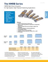
• High dynamic control for precision positioning • High payload capacity • High speed operation • Easy installation • Highly configurable design • Ideal in multi axis applications • 5 different frame sizes to choose from • Basic or reinforced profiles for supported or unsupported applications • Tandem carriage with second carriage for higher load capabilities • Bi-parting carriage for centering applications • Long available strokes • Complete motor and drive packages • Ambient operating temperature range -20°C to +80°C • IP 54 Rating Belt Driven Tables The HMRB is the belt driven version in the...
Open the catalog to page 3
Drive shaft Designed to pair with a large assortment of motor and gearhead options Steel reinforced timing belt High thrust force transmission and long life Carriage assembly Low profile, high strength aluminum construction with threaded and pinning mounting options Carriage Options Standard carriage or tandem carriage for higher load capabilities Cover Options IP20 rated without protective cover, or IP54 rated protective cover with seal strip cover assemblies— ideal for harsh environments Motor Mounting Options The HMRB belt driven positioner is designed to optimize flexibility in Easy access...
Open the catalog to page 4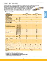
SPECIFICATIONS Parker Hannifin's High Moment Rodless (HMR) Series electric linear actuator is one of the most user friendly and versatile actuator lines on the market today. Guided by two square rail bearings, the HMR has enormous moment and payload capacity bundled in a low-profile, yet sleek package. With five different frame sizes, two different drive train options, multiple mounting, carriage and sensor options, and an IP54 protective cover option—along with a multitude of other customizable features—the HMR was truly designed with flexibility in mind. Common Specifications Note- For force...
Open the catalog to page 5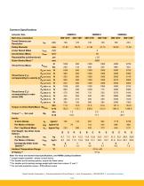
Common Specifications Actuator Size HMRB15 HMRB18 HMRB24 Note- For force and moment load specifications, see HMRB Loading Conditions (1) Longer lengths available - please consult factory (2) For tandem and bi-parting options, double the listed values (3) For tandem and bi-parting carriage weight add mass from column '0' and '1' (4) For unit with protective covers - IP20 without covers Parker Hannifin Corporation • Electromechanical & Drives Division • Irwin, Pennsylvania • 800-358-9070 • www.parker.com/emn
Open the catalog to page 6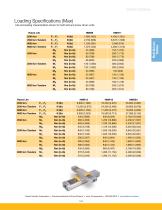
Loading Specifications (Max) Life and loading characteristics shown for both belt and screw driven units.
Open the catalog to page 7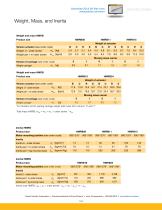
Weight and mass HMRB Product size HMRB08 HMRB11 HMRB15 Inertia total HMRB: Jtot = J0 + order stroke * Jmt + mC * Jkg + m * Jkg Parker Hannifin Corporation • Electromechanical & Drives Division • Irwin, Pennsylvania • 800-358-9070 • www.parker.com/emn 16
Open the catalog to page 8
HMR Loading Conditions Loading conditions, including external forces and moment loading, are application dependent. The center of gravity for the mass/payload attached to the carriage must be determined in order to properly size the ideal actuator for your application. Please note that when selecting the proper HMR actuator for your system the sum of all loading should not exceed "1" as per the formula below. Belt Driven Tables Calculating Load Factors - Combined Normal and Moment Load The sum of combined loads (static and dynamic) must not exceed “1” at any time as shown in the formula below:...
Open the catalog to page 9All Parker Electromechanical and Drives Division Europ catalogs and technical brochures
 AC15 Variable Speed Drive
16 Pages
 Belt Driven
32 Pages
 SensoNODETM
2 Pages
 Medical solutions
2 Pages
 RS and AXEM Series
14 Pages
 AC890
AC89025 Pages
 HPLA Linear Actuators
40 Pages
 AC10 Variable Speed Drive
26 Pages
 AC30 Variable Speed Drive
42 Pages
 Parker Automation Controller
20 Pages
 Explosion Proof Servo Motors
44 Pages
 Parker Gearboxes
36 Pages
Archived catalogs
 GVM Global Vehicle Motor
24 Pages
 Frameless Servo Motors
44 Pages
 ETH Electro Cylinder_2019
60 Pages
 GVI Global Vehicle Inverter
16 Pages
 RTS, RS, RX and AXEM Series
24 Pages
 Motion Solutions
16 Pages
 PE Series
12 Pages
 PSD1 Parker Servo Drive
12 Pages
 DC590+ Product Catalog
20 Pages
 PSD1 Parker Servo Drive
16 Pages
 ETHERNET Powerlink
20 Pages
 PTN Planetary Gearbox
4 Pages
 PS / RS Series
16 Pages
 HKW Series
133 Pages
 SMB Motors
28 Pages
 Torque Motors – Kit version
111 Pages
 TMW Series Torque Motors
32 Pages
 DC590P
28 Pages
 ETH Electro Cylinder_2012
56 Pages


- Cylinder
- Parker electric actuator
- Coaxial gearhead
- Parker positioning stage
- Precision gearhead
- Hydraulic cylinder
- Parker linear positioning stage
- Parker servomotor
- Solid-shaft gearhead
- Pneumatic cylinder
- Gear train gear reducer
- Motorized positioning table
- Servo-amplifier
- Gearbox for industrial applications
- Compact actuator
- Parker precision positioning stage
- Parker performance servomotor