- Catalogs
- Pantron Instruments GmbH
- Photo-electric Amplifier ISG-N14
Photo-electric Amplifier ISG-N14
1 /5Pages

Photo-electric Amplifier ISG-N14
1 /5Pages
Catalog excerpts
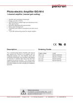
Photo-electric Amplifier ISG-N14 1-channel amplifier (manual gain setting) • Amplifier with modulated infrared light • Range up to 35 m (115 ft) • high immunitity to ambient light and interference from other light barriers • Sensitivity adjustable with potentiometer • Relay output (changeover) • Transmitter and receiver connections are short-circuit proof • 11-pin DIN railmounting socket for simple installion Ordering Guide The 1-channel photo-electric Amplifier with manual gain setting from Pantron is an amplifier with an integrated analysis unit. The amplifier works with modulated infrared light, which enables a high degree of immunity to ambient light and cross talk from neighbouring photo-sensors. The manual gain setting, adjusted with a potentiometer located on the front side, enables the user to simplify the installation and work. Safety Instructions The operation of infrared amplifier ISG... is not authorized for applications where safety of the person depends on the device function. Pantron Instruments GmbH • Postfach 1129 • D-31158 Bad Salzdetfurth • Tel.: 05063/9591-0
Open the catalog to page 1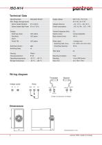
ISG-N14 Technical Data Operating basis Modulated IR-light Supply voltage Voltage tolerance Power consumption Max. Range (through beam) Sensor heads Standard Sensor heads High Power 35 m (115 ft) Display: Switching status System power manuel adjustable Basic transmit level Relay output Switching data (max.) Switching function Switching delay Switching frequency Test input Housing protection Mounting orientation Operating temperature Storage temperature Wiring diagram (Farben für Sensoren mit Kabel) January 2002, subject to chan
Open the catalog to page 2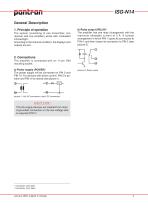
ISG-N14 General Description 1. Principle of operation The system (consisting of one transmitter, one receiver and one amplifier) works with modulated infrared light. According to the channel condition, the displays and outputs are set. b) Relay output (RELAY)1 The amplifier has one relay (changeover) with the maximum allowable current of 5 A. A contact arrangement in which PIN 1 opens its connection to PIN 4, and then closes its connection to PIN 3 (see picture 2). 2. Connections The amplifier is connected with an 11-pin DIN mounting socket. a) Power supply (POWER)1 The power supply will be connected...
Open the catalog to page 3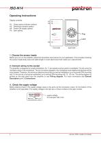
Output status indicator (yellow) Sensitivity indicator (green) Power ON display (green) Gain setting RELAY-STATUS GAIN-CONTROL ISG-N14/230VAC amplifier, manual gain, relay Version: 01/01 front side back side 1. Choose the sensor heads Before you turn on the amplifier, select the transmitter and receiver for your application. This includes choosing the sensor heads body style and cable length or quick disconnect that meets your requirements. 2. Connect wiring to the socket The amplifier is designed for simple installation. An 11-pin socket must be used for installation. Do not cover the ventilation...
Open the catalog to page 4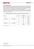
ISG-N14 5. Operating procedure Plug the amplifier into the socket and switch the power supply on. The Power ON indicator H4 (POWER ON)² lights green. To guarantee the regular operation of the infrared amplifier, the sensitivity must be adjusted manually. For this, turn the potentiometer P3 (GAIN-SETTING)² from the left side to the right side until the green sensitivity indicator H2 (GAIN-CONTROL)² is lit constantly. As the potentiometer is adjusted to the right side, the amplifier will become less sensitive. For description of how the switching output works, see table 1. After adjustment, the...
Open the catalog to page 5All Pantron Instruments GmbH catalogs and technical brochures
 Light Bar Light Barrier
2 Pages

- Photoelectric sensor
- Rectangular photoelectric sensor
- Light barrier
- Safety light curtain
- Through-beam light curtain
- DC amplifier
- Infrared photoelectric sensor
- Cylindrical photoelectric sensor
- Single-channel amplifier
- Waterproof photoelectric sensor
- DIN rail amplifier
- Compact amplifier
- Optical sensor
- IP67 photoelectric sensor
- Light sensor
- Adjustable amplifier
- Miniature photoelectric sensor
- High-power amplifier
- 2-channel amplifier
- Infrared sensor