
- Catalogs
- Panasonic Robot & Welding system solutions
- Power Choke Coil


- Company
- Products
- Catalogs
- News & Trends
- Exhibitions
Power Choke Coil

Power Choke Coil
- High Heat Resistance: Operates up to 150°C, including self-heating.
- High Reliability: Maintains inductance stability under high DC current and temperature conditions, with high vibration resistance.
- High Bias Current: Utilizes ferrous alloy magnetic material for excellent inductance stability.
- Temperature Stability: Stable inductance over a broad temperature range.
- Low Audible Noise: Achieved through a gapless structure with a metal composite core.
- High Efficiency: Features low DC resistance and low eddy-current loss.
- Shielded Construction: Provides additional protection and performance stability.
- Noise filters for drive circuitry requiring high temperature operation and peak current handling.
- Boost-Converter and Buck-Converter DC/DC applications.
- Operating Temperature Range: -40°C to +150°C (including self-temperature rise).
- Storage Conditions: -5°C to +35°C, 85% RH max.
- Standard Packing Quantity: Varies by model, ranging from 1,000 to 2,000 pcs/box.
- Inductance vs DC Current: Detailed graphs provided for various models, showing inductance stability under different DC bias conditions.
- Case Temperature vs DC Current: Performance varies based on PWB conditions, with specific heat dissipation characteristics noted.
- Design and specifications are subject to change without notice; consult the factory for current specifications before purchase or use.
- Solderability is guaranteed for one year; expired products should not be used.
- For higher operating temperature conditions, contact a Panasonic representative.
Catalog excerpts
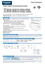
Power Inductors Panasonic INDUSTRY High heat resistance and high reliability using metal composite core (MC) Industrial Property : patents 21 (Registered 2/Pending 19) • High heat resistance : Operation up to 150 °C including self-heating • High-reliability : High vibration resistance as result of newly developed integral construction; under severe reliability conditions of automotive and other strenuous applications • High bias current : Excellent inductance stability using ferrous alloy magnetic material (Fig.1) •Temp. stability : Excellent inductance stability over broad temp. range (Fig.1) • Low audible (buzz) noise : A gapless structure achieved with metal composite core • High efficiency : Low DC resistance of winding and low eddy-current loss of the core • Shielded construction •AEC-Q200 compliant • RoHS compliant • Noise filter for various drive circuitry requiring high temp. operation and peak current handling capability • Boost-Converter, Buck-Converter DC/DC Product Code Classification Height Winding Inductance Core Suffix Size Design and specifications are each subject to change without notice. Ask factory for the current technical specifications before purchase and/or use. Should a safety concern arise regarding this product, please be sure to contact us immediately.
Open the catalog to page 1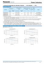
Power Inductors 1. Series PCC-M0530M/PCC-M0540M (ETQP3M□□□YFP/ETQP4M□□□YFP) Standard Parts *1: Measured at 100 kHz *2: DC current which causes temperature rise of 40K. Parts are soldered by reflow on four-layer PWB(1.6 mm FR4) and measured at room temperature. See also ✽5 *3: DC current which causes temperature rise of 40K. Parts are soldered by reflow on multilayer PWB with high heat dissipation performance. Note: Heat radiation constant are approx. 52 K/W measured on 5.5×5.0×3.0 mm case size and approx. 48 K/W measured on 5.5×5.0×4.0 mm case size. See also (✽5) *4: Saturation rated current...
Open the catalog to page 2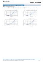
Power Inductors Performance Characteristics (Reference 2) ● Case Temperature vs DC Current PWB condition A : Four-layer PWB (1.6 mm FR4), See also ✽2 PWB condition B : Multilayer PWB with high heat dissipation performance. See also ✽3 [ ETQP3M3R3YFP ] Design and specifications are each subject to change without notice. Ask factory for the current technical specifications before purchase and/or use. Should a safety concern arise regarding this product, please be sure to contact us
Open the catalog to page 3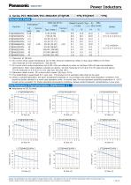
Power Inductors 2. Series PCC-M0630M/PCC-M0645M (ETQP3M□□□YFN/ETQP4M□□□YFN) Standard Parts *1: Measured at 100 kHz *2: DC current which causes temperature rise of 40K. Parts are soldered by reflow on four-layer PWB(1.6 mm FR4) and measured at room temperature. See also ✽5 *3: DC current which causes temperature rise of 40K. Parts are soldered by reflow on multilayer PWB with high heat dissipation performance. Note: Heat radiation constant are approx. 44 K/W measured on 6.5×6.0×3.0 mm case size and approx. 37 K/W measured on 6.5×6.0×4.5 mm case size. See also (✽5) *4: Saturation rated current...
Open the catalog to page 4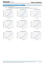
Power Inductors Performance Characteristics (Reference 2) ● Case Temperature vs DC Current PWB condition A : Four-layer PWB (1.6 mm FR4), See also ✽2 PWB condition B : Multilayer PWB with high heat dissipation performance. See also ✽3 Design and specifications are each subject to change without notice. Ask factory for the current technical specifications before purchase and/or use. Should a safety concern arise regarding this product, ple
Open the catalog to page 5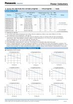
Power Inductors 3. Series PCC-M0754M/PCC-M750M (ETQP5M□□□YFM/ETQP5M□□□YGM) Standard Parts *1: Measured at 100 kHz *2: DC current which causes temperature rise of 40K. Parts are soldered by reflow on four-layer PWB(1.6 mm FR4) and measured at room temperature. See also ✽5 *3: DC current which causes temperature rise of 40K. Parts are soldered by reflow on multilayer PWB with high heat dissipation performance. Note: Heat radiation constant is approx. 31 K/W measured on 7.5×7.0×5.4 mm case size and approx. 29 K/W measured on 7.5×7.0×5.0 mm case size. See also (✽5) *4: Saturation rated current :...
Open the catalog to page 6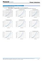
Power Inductors Performance Characteristics (Reference 2) ● Case Temperature vs DC Current PWB condition A : Four-layer PWB (1.6 mm FR4), See also ✽2 PWB condition B : Multilayer PWB with high heat dissipation performance. See also ✽3 [ ETQP5M4R7YFM ] Design and specifications are each subject to change without notice. Ask factory for the current technical specifications before purchase and/or use. Should a safety concern arise regarding this product, ple
Open the catalog to page 7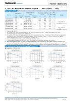
Power Inductors 4. Series PCC-M0854M/PCC-M0850M (ETQP5M□□□YFK/ETQP5M□□□YGK) Standard Parts *1: Measured at 100 kHz *2: DC current which causes temperature rise of 40K. Parts are soldered by reflow on four-layer PWB(1.6 mm FR4) and measured at room temperature. See also ✽5 *3: DC current which causes temperature rise of 40K. Parts are soldered by reflow on multilayer PWB with high heat dissipation performance. Note: Heat radiation constant are approx. 27 K/W measured on 8.5×8.0×5.4 mm case size and approx. 29 K/W measured on 8.5×8.0×5.0 mm case size. See also (✽5) *4: Saturation rated current...
Open the catalog to page 8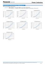
Power Inductors Performance Characteristics (Reference 2) ● Case Temperature vs DC Current PWB condition A : Four-layer PWB (1.6 mm FR4), See also ✽2 PWB condition B : Multilayer PWB with high heat dissipation performance. See also ✽3 Design and specifications are each subject to change without notice. Ask factory for the current technical specifications before purchase and/or use. Should a safety concern arise regarding this product, please be sur
Open the catalog to page 9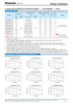
Power Inductors 5. Series PCC-M1054M/PCC-M1050M (ETQP5M□□□YFC/ETQP5M□□□YGC) Standard Parts *1: Measured at 100 kHz *2: DC current which causes temperature rise of 40K. Parts are soldered by reflow on four-layer PWB(1.6 mm FR4) and measured at room temperature. See also ✽5 *3: DC current which causes temperature rise of 40K. Parts are soldered by reflow on multilayer PWB with high heat dissipation performance. Note: Heat radiation constant are approx. 23 K/W measured on 10.7×10.0×5.4 mm case size and approx. 26 K/W measured on 10.7×10.0×5.0 mm case size. See also (✽5) *4: Saturation rated current...
Open the catalog to page 10All Panasonic Robot & Welding system solutions catalogs and technical brochures
 Multi-Purpose Robot LA-1800
4 Pages
 POSITIONERS & PERIPHERALS
2 Pages
 PC-Software DTPS
10 Pages
 PerformArc Welding Systems
12 Pages
 Robot Welding Torches
2 Pages
 Wire Booster
2 Pages


Archived catalogs
 POSCAP
40 Pages
 Electric Double Layer Capacitors
12 Pages
 PAN1326C2
1 Page
 Panasonic Torches
2 Pages
 PAN1326 Design Guide
22 Pages
 PAN9026
82 Pages
 PAN1326C
40 Pages
 PAN9420 Command Specification
95 Pages
 PAN1762
17 Pages
 Drive systems Catalogue 2019
12 Pages
 Wireless Connectivity 2019
2 Pages
 PAN1326C2 2019
48 Pages
 802.15.4-Modem PAN4580
2 Pages
 EMERGENCY LIGHTING
2 Pages
 EUROPEAN E-CALL
2 Pages
 PAN1761
2 Pages
 PAN1740
41 Pages
 PAN1760A
2 Pages
 SOFT PYROLYTIC GRAPHITE
2 Pages
 WEARABLES LI-ION PIN-TYPE
2 Pages
 SMD Lytic Capacitor V Chip
2 Pages
 E-Bike Systems
12 Pages
 WIRELESS CONNECTIVITY
2 Pages
 Pin-type Li-ion batteries
2 Pages
 Batteries Short-Form-Catalog
52 Pages
 Microcomputer
24 Pages
 YD-350GB2
2 Pages
 TAWERS Hyper Dip Pulse
2 Pages
 SP-MAG Process
2 Pages
 PerformArc Automotive
1 Page
 TIG Filler System
1 Page
 PerformArc C Series
1 Page
 PerformArc TT Series
1 Page
 PerformArc MT Series
1 Page
 PerformArc ET Series
1 Page
 TAWERS Zi-Tech Process
2 Pages
 Handling Robots YS080G3
2 Pages
 Handling robots HS-G3 Series
4 Pages
 Welding Systems Solutions
12 Pages
 Welding Robots G3 Series
6 Pages
 Panasonic G3 Welding Robots
6 Pages
 TAWERS WG3 Series
12 Pages
 WG3 Welding Robots
12 Pages
 G3 Robot Controller
1 Page
 Panasonic Positioner
4 Pages
 TAIWERS-Welding Solution
12 Pages
 Handling Robots
2 Pages
 Positioners
4 Pages
 Welding Power Sources
2 Pages
 DTPS-G3
4 Pages
 DTPS G3-Software
4 Pages
 Panasonic Eco ideas
2 Pages


- Welding system
- Panasonic industrial robot
- Automation software solution
- Management software solution
- Analysis software solution
- Automatic welding machine
- Real-time software
- Panasonic articulated robot
- Control software
- Servo-motor
- Panasonic 6-axis robot
- Monitoring software solution
- Handling robot
- Floor-mounted robot
- 3D software solution
- Inspection system
- Visualization software solution
- Simulation software solution
- AC servo-motor
- Metal welding machine