- Catalogs
- Panasonic Robot & Welding system solutions
- PAN1326C2 2019
- Company
- Products
- Catalogs
- News & Trends
- Exhibitions
PAN1326C2 2019
1 /48Pages

PAN1326C2 2019
1 /48Pages
Catalog excerpts

PAN1326C2 Bluetooth Basic Data Rate and Low Energy Module
Open the catalog to page 1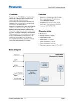
Parasonic PAN1326C2 Bluetooth Module Overview Panasonic's new PAN1326C2 is a Host Controlled Interface (HCI) Bluetooth Radio Frequency (RF) module that brings Texas Instruments Incorporated™ seventh generation Bluetooth core integrated circuit, the CC2564C, to an easy-to-use module format. The PAN1326C2 is Bluetooth 4.2 compliant and it offers best-in-class RF performance with about twice the range of other Bluetooth Low Energy solutions. Panasonic's tiny footprint technology has produced a module of only 85.5 mm2. The module is designed to accommodate PCBs pad pitch of 1.3 mm and as few as two...
Open the catalog to page 2
By purchase of any of the products described in this document the customer accepts the document's validity and declares their agreement and understanding of it is contents and recommendations. Panasonic reserves the right to make changes as required at any time without notification. Please consult the most recently issued Product Specification before initiating or completing a design. © Panasonic Industrial Devices Europe GmbH 2019. This Product Specification is copyrighted. Reproduction of this document is permissible only if reproduction is without alteration and is accompanied by all associated...
Open the catalog to page 3
Parasonic PAN1326C2 Bluetooth Module Product Specification Rev. 1.1 Page 4
Open the catalog to page 4
Parasonic PAN1326C2 Bluetooth Module 1 About This Document 1.1 Purpose and Audience This Product Specification provides details on the functional, operational, and electrical characteristics of the Panasonic PAN1326C2 module. It is intended for hardware design, application and Original Equipment Manufacturer (OEM) engineers. The product is referred to as “the PAN1326C2” or “the module” within this document. Please refer to the Panasonic website for related documents ^ 7.2.2 Product Information. Product Specification Rev. 1.1 Page 6
Open the catalog to page 6
PAN1326C2 Bluetooth Module 2 Overview 2 Overview Panasonic’s new PAN1326C2 is a Host Controlled Interface (HCI) Bluetooth RF module that brings Texas Instrument’s seventh generation Bluetooth core integrated circuit, the CC2564, to an easy-to-use module format. The PAN1326C2 is Bluetooth 4.2 compliant and it offers best in class RF performance with about twice the range of other Bluetooth Low Energy solutions. Panasonic’s tiny footprint technology has produced a module of only 85.5 mm². The module is designed to accommodate PCBs pad pitch of 1.3 mm and as few as two layers for easy implementation...
Open the catalog to page 7
PAN1326C2 Bluetooth Module 2 Overview The I/O are 1.8 V driven and might need external level shifter and Low-dropout regulator (LDO). The Pin MLDO_OUT cannot be used as reference due to RF internal connection. The total capacity will not exceed 2.8 µF. The total inductance will not exceed 0 nH. There are no voltage multiplying or voltage boosting circuits.
Open the catalog to page 8
Parasonic PAN1326C2 Bluetooth Module Product Specification Rev. 1.1 Page 9 I =input, O=output, I/O=bidirectional, P=power, PU=pulled up, PD=pulled down I/O Type: Digital I/O cells, HY=input hysteresis, current=typ. output current No signals are allowed on the I/O pins if no VDD_IO (Pin 22) power supplied, except pin 7, 8, 17-19.
Open the catalog to page 9
Parasonic PAN1326C2 Bluetooth Module 2 Overview For RF conducted measurements de-solder the antenna and solder an antenna connector to the hot pin. HCI_CTS is an input signal to the CC2564C device: • When HCI CTS is low: CC2564C is allowed to send data to Host device. • When HCI_CTS is high: CC2564C is not allowed to send data to Host device. 4 I=input, O=output, I/O=bidirectional, P=power, PU=pulled up, PD=pulled down 5 I/O Type: Digital I/O cells, HY=input hysteresis, current=typ. output current Product Specification Rev. 1.1 Page 10
Open the catalog to page 10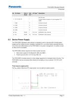
Parasonic PAN1326C2 Bluetooth Module 2.3 Device Power Supply The PAN1326C2 Bluetooth radio solution is intended to work in devices with a limited power budget such as cellular phones, headsets, handheld PC’s, and other battery-operated devices. One of the main differentiators of the PAN1326C2 is its power management. It is ability to draw as little current as possible. The PAN1326C2 device requires two kinds of power sources: • Main power supply for the Bluetooth (VDD_IN=VBAT) • Power source for the 1.8 V I/O ring (VDD_IO) The PAN1326C2 includes several on-chip voltage regulators for increased...
Open the catalog to page 11
PAN1326C2 Bluetooth Module 2 Overview Full-DC2DC system (Lower RF output power, but optimum system power): Mixed DC2DC-VBAT system (Maximum RF output power and optimum system power, but requires routing of VBAT): Clock Inputs The Slow Clock is always supplied from an external source. It is connected to the SLOW_CLK_IN pin number 8 and can be a digital signal with peak to peak of 0 V to 1.8 V. The Slow Clock's frequency accuracy must be 32.768 kHz 250 ppm for Bluetooth usage (according to the Bluetooth specification). The Slow Clock 32.768 kHz is mandatory to start the internal controller; otherwise...
Open the catalog to page 12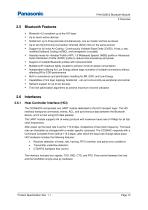
PAN1326C2 Bluetooth Module 2 Overview Bluetooth Features • • • • • • Support of multiple Bluetooth profiles with enhanced QoS Assisted mode for Handset Profile (HFP) 1.6 Wideband Speech (WBS) profile or Advanced Audio Distribution Profile (A2DP) profile to reduce host processing and power Bluetooth 4.2 compliant up to the HCI layer Built-in coexistence and prioritization handling for BR, EDR, and Low Energy Up to seven active devices Scatternet: up to three piconets simultaneously, one as master and two as slaves Up to two Synchronous Connection Oriented (SCO) links on the same piconet Support...
Open the catalog to page 13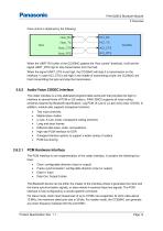
PAN1326C2 Bluetooth Module 2 Overview Flow control is obtained by the following: When the UART RX buffer of the CC2564C passes the “flow control” threshold, it will set the signal UART_RTS high to stop transmission from the host. When the signal UART_CTS is set high, the CC2564C will stop it is transmission on the interface. In case HCI_CTS is set high in the middle of transmitting a byte, the CC2564C will finish transmitting the byte and stop the transmission. Audio/Voice CODEC Interface The codec interface is a fully-dedicated programmable serial port that provides the logic to interface to...
Open the catalog to page 14All Panasonic Robot & Welding system solutions catalogs and technical brochures
 Multi-Purpose Robot LA-1800
4 Pages
 POSITIONERS & PERIPHERALS
2 Pages
 PC-Software DTPS
10 Pages
 PerformArc Welding Systems
12 Pages
 Robot Welding Torches
2 Pages
 Wire Booster
2 Pages


Archived catalogs
 POSCAP
40 Pages
 Power Choke Coil
19 Pages
 Electric Double Layer Capacitors
12 Pages
 PAN1326C2
1 Page
 Panasonic Torches
2 Pages
 PAN1326 Design Guide
22 Pages
 PAN9026
82 Pages
 PAN1326C
40 Pages
 PAN9420 Command Specification
95 Pages
 PAN1762
17 Pages
 Drive systems Catalogue 2019
12 Pages
 Wireless Connectivity 2019
2 Pages
 802.15.4-Modem PAN4580
2 Pages
 EMERGENCY LIGHTING
2 Pages
 EUROPEAN E-CALL
2 Pages
 PAN1761
2 Pages
 PAN1740
41 Pages
 PAN1760A
2 Pages
 SOFT PYROLYTIC GRAPHITE
2 Pages
 WEARABLES LI-ION PIN-TYPE
2 Pages
 SMD Lytic Capacitor V Chip
2 Pages
 E-Bike Systems
12 Pages
 WIRELESS CONNECTIVITY
2 Pages
 Pin-type Li-ion batteries
2 Pages
 Batteries Short-Form-Catalog
52 Pages
 Microcomputer
24 Pages
 YD-350GB2
2 Pages
 TAWERS Hyper Dip Pulse
2 Pages
 SP-MAG Process
2 Pages
 PerformArc Automotive
1 Page
 TIG Filler System
1 Page
 PerformArc C Series
1 Page
 PerformArc TT Series
1 Page
 PerformArc MT Series
1 Page
 PerformArc ET Series
1 Page
 TAWERS Zi-Tech Process
2 Pages
 Handling Robots YS080G3
2 Pages
 Handling robots HS-G3 Series
4 Pages
 Welding Systems Solutions
12 Pages
 Welding Robots G3 Series
6 Pages
 Panasonic G3 Welding Robots
6 Pages
 TAWERS WG3 Series
12 Pages
 WG3 Welding Robots
12 Pages
 G3 Robot Controller
1 Page
 Panasonic Positioner
4 Pages
 TAIWERS-Welding Solution
12 Pages
 Handling Robots
2 Pages
 Positioners
4 Pages
 Welding Power Sources
2 Pages
 DTPS-G3
4 Pages
 DTPS G3-Software
4 Pages
 Panasonic Eco ideas
2 Pages


- Welding system
- Panasonic industrial robot
- Automation software solution
- Management software solution
- Analysis software solution
- Automatic welding machine
- Real-time software
- Panasonic articulated robot
- Control software
- Panasonic 6-axis robot
- Servo-motor
- Monitoring software solution
- Floor-mounted robot
- 3D software solution
- Handling robot
- Inspection system
- Visualization software solution
- Simulation software solution
- Metal welding machine
- Programming software