
Catalog excerpts
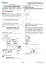
For in-depth information on carrying out the basic settings in the environmental configuration mode refer to the "Basic Settings" sheet at the end of this "Easy User Guide". The functionality of the MODE button and the SET button is the same for every software package. This guide provides an example that leads you from the startup to a functioning application. Besides, you learn about the basic functions of your LightPix. Depending on your experience, you need between 30 and 60 minutes to work through the example. The following diagram shows where the operation buttons are located on the operation unit and which functions the operation buttons have: Working with the operation buttons Please note the safety instructions in your manual and the "NAiS LightPix AE10" leaflet. For the following examples you need a finder unit, an operation unit, a main unit and cables. For an explanation of system components, part names and dimensions, refer to the "NAiS LightPix AE10" leaflet included in the package. For in-depth information, refer to your manual. 1. Assemble the LightPix according to the leaflet 1. MODE 2. Connect the power cable by soldering the wires to the connectors Figure 2: Operation buttons diagram For an overview of the MODE button, see Figure 1 For procedure and pin assignment, see the leaflet. 2. SET 3. Mount the main unit at the correct distance from the target object 3. PRMT (Parameters) For an overview of the SET mode, see Figure 1 For the correct distance, refer to the table in the leaflet. Switch the setting items when you are in SET mode or when setting upper/lower limits. In TEACH mode the buttons move the checker size/shape in X-direction (see also Figure 3 ). > Your LightPix is delivered with one of the following four software packages: 4. TYPE Color Extraction (Product number: ANE10x0) You can choose from 7 different sets of parameters ("Teachings"). TYPE selects these "Teachings" in RUN mode and switches between exposure time, checker size and checker move in TEACH mode. Press the TYPE button and keep the SET button pressed at the same time to switch types ("Teachings") in TEACH mode. For this example you do not need to do this. Edge Detection (Product number: ANE10x1) Size Measurement (Product number: ANE10x2) Matching (Product number: ANE10x3) This "Easy User Guide" is for the "Size Measurement" software package . Working with the operation modes You can adjust the checker size in TEACH mode for all software packages with the TYPE, PRMT, UP/DOWN buttons. (Checker size = selected area in the field of view to be analyzed The LightPix possesses different operation modes. To switch between them, press the MODE or SET button of your operation unit for 3s or 1s: field of view = maximum area to be analyzed). > Teaching Mode C. TOLERANCE RANGE MODE 3s MODE 1s Power ON SET 3s D. INSPECTION Inspection Modes B. IMAGE CAPTURING/TEACHING RUN Mode V IEW Mode - High-speed inspection - No image on finder unit's screen - Inspection 300ms slower - Image on finder units screen RUN- Figure 3: PRMT, TYPE and TRIGGER buttons 5. TRIGGER RUN/RUN-VIEW mode: Executes one inspection TEACH mode: Executes teaching (see also > MODE 1s Figure 3) > SET 1s SET 1s 6. UP/DOWN Change a tolerance value or a setting value in the SET mode. > A. BASIC SETTINGS Environmental Configuration Mode SET Mode SET 1s Figure 4: UP/DOWN buttons Figure 1: Operation mode diagram Notes: General rule to exit a mode: Press the same button you pressed to enter the mode for 1s. >
Open the catalog to page 1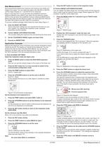
Size measurement detects the maximum and minimum size (width and height) of an object. You can select the object color (BLACK or WHITE) and the object direction (X, Y and BOTH) to be measured. > You can register the object target size, the binary levels and the exposure time in order to get the optimum binary image. Please register the "OK H- armature" to get the correct object size. Keep in mind that OUT1 is only set when the predefined maximum distances [MAdX] and/or [MAdY] stay within the set tolerance ranges. OUT2 is only set when the predefined minimum distances [MIdX] and/or [MIdY]...
Open the catalog to page 2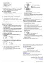
Figure 12: Checker move > - T maxx + T maxx Position the white rectangle such that the "OK H-armature" fits into the middle. Your settings are registered automatically. > Now you have registered the "OK H-armature". When the registered target size is correct, [dOnE] is displayed on the operation unit (see also Figure 15: Tolerance setting diagram for size measurement Figure 8 ). > The lines on which the minimum distance [MIdX] and the maximum distance [MAdX] were found are displayed in white (see also > Figure 16 ). Press the UP/DOWN buttons to switch between the [MIdX] (=d2) and [MAdX]...
Open the catalog to page 3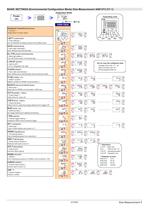
BASIC SETTINGS (Environmental Configuration Mode) Size Measurement ANE10*2 (V1.1) > 07/2004 Size Measurement 5 >
Open the catalog to page 5All Panasonic Electric Works Europe catalogs and technical brochures
-
 FM-200
12 Pages
-
 FPWIN Pro
8 Pages
-
 Automation Controls Catalog
14 Pages
-
 GX-F/H SERIES
16 Pages
-
 FOR SENSORS PRODUCT FINDER
2 Pages
-
 Short form SENSORS
124 Pages
-
 Programmable Logic Controllers
32 Pages
-
 IONIZER
36 Pages
-
 PhotoMOS Catalog
354 Pages
-
 Catalog Automotive Relays
210 Pages
-
 AC Servo
155 Pages
-
 Sensor short form
132 Pages
-
 MINAS A5 SERVO DRIVES
28 Pages
-
 HIGHLIGHTS FOR ECO INNOVATIONS
12 Pages
-
 Catalogue-connectors
158 Pages
-
 Fire alarm systems 2013
28 Pages
-
 Shortform Temperature Controller
28 Pages
-
 ELECTROMECHANICAL RELAYS
626 Pages
-
 EY 7443 Auto Drill & Driver
2 Pages
-
 Sealing Guns 2012/2013
8 Pages
-
 New Products Autumn 2012
20 Pages
-
 Catalog MINAS A5 series
85 Pages
-
 FP-Safe catalog
12 Pages
-
 Overview HMI
36 Pages
-
 Overview Eco-POWER METERs
20 Pages
-
 Panasonic Automation Products
28 Pages
-
 Catalog built-in sensors
66 Pages
-
 Catalog Microwave Devices
69 Pages
-
 LC4H - digital counter
9 Pages
-
 Limit switches AZH
14 Pages
-
 Fire alarm system 2011/2012
28 Pages
-
 Imagechecker P400XD
20 Pages
-
 2D Code Reading Sensor PD60 / 65
12 Pages
-
 FP-e: PLC for panel mounting
8 Pages
-
 UJ30/35
12 Pages
-
 GN-series touch terminals
36 Pages
-
 Eco-power meters
16 Pages
-
 Laser markers
28 Pages
-
 Catalog timers & counters
160 Pages
-
 Catalog limit switches
52 Pages
-
 PHOTOMOS & SOLID STATE RELAYS
356 Pages
-
 Catalog Switches
186 Pages


Archived catalogs
-
 P400MA and P400 Imagecheckers
20 Pages
-
 Turquoise switch series
28 Pages
-
 Catalogue operation switches
156 Pages
-
 R-1755 R-1650
2 Pages
-
 Laserdrillable Prepreg
1 Pages
-
 R-1566W R-1551W
1 Pages
-
 MC-100EX/MS
1 Pages
-
 Base 2324
2 Pages
-
 Heat detectors 4375 and 4376
2 Pages
-
 Multi detector 4350
2 Pages
-
 Addressable siren 3377
2 Pages
-
 External power supply 3366
2 Pages
-
 Analog base 3312F / FL
2 Pages
-
 Analog base 3312
2 Pages
-
 Analog multi detector 4300
2 Pages
-
 Analog heat detector 3308
2 Pages
-
 Fire alarm system EBL128
2 Pages
-
 Fire alarm system EBL512
2 Pages
-
 Dicool
24 Pages
-
 Eco-POWER METER KW4S
6 Pages
-
 KW4M Eco-POWER METER
4 Pages
-
 KW8M Eco-POWER METER
8 Pages
-
 S1DX – analog timer
6 Pages
-
 PM4H-W - analog timer - twin
5 Pages
-
 PM4H - analog timer
6 Pages
-
 PM5S - analog DIN-rail timer
7 Pages
-
 QM4H - digital timer
4 Pages
-
 LT4H-W
8 Pages
-
 LT4H - digital timer
6 Pages
-
 KR20 Wireless Unit
8 Pages
-
 PV500 Imagechecker
20 Pages
-
 Micro-Imagechecker AX30/AX40
16 Pages
-
 PV310 Micro-Imagechecker
12 Pages
-
 LightPix AE20
4 Pages
-
 PD60/65 2D Code Readers
6 Pages
-
 Panasonic Automation Products
12 Pages
-
 Push Button Switches - ND Series
41 Pages
-
 Push Button Switches - NS Series
11 Pages
-
 AJ9 (J9) SWITCHES
6 Pages
-
 AJ7 (J7) SWITCHES
8 Pages
-
 AJ4 (J4) TOGGLE SWITCHES
6 Pages
-
 TURQUOISE SNAP SWITCHES (AJN1/2)
10 Pages
-
 Catalogue snap action relays
124 Pages
-
 Electromechanical Relays
571 Pages
-
 P400 and P400S
20 Pages
-
 Micro-Imagechecker AX40
16 Pages
-
 Brochure "2D Code Reader PD50"
12 Pages
-
 A-Series
6 Pages
-
 Brochure "LightPix AE20"
4 Pages
-
 Imagechecker Brochure
32 Pages
-
 Easy User Guide 'Matching'
5 Pages


