
Catalog excerpts

Partly Order Discontinued as of August 31, 2012 DIN24 SIZE MULTI-RANGE ANALOG TIMER C-UL File No.: E59504 (Vol. 3) Features • 24-240V AC/DC free-voltage input • Built-in Screw terminals • 6 different operation modes: (PM5S-A) • Multiple time ranges — 1 s to 500 h (Max.) • Slim body — DIN 22.5 mm .886 inch • 0 setting instantaneous output operation • UL/C-UL/CE approval RoHS Directive compatibility information http://www.nais-e.com/ Product types Type Contact arrangement Operation mode 6 operation modes • Pulse ON-delay • Pulse Flicker • Pulse ON-flicker • Signal OFF-delay • Pulse One-shot • Pulse One-cycle Power ON-delay Relay Timed-out 2 Form C 6 operation modes (With instantaneous contact) • Pulse ON-delay • Pulse Flicker • Pulse ON-flicker • Signal OFF-delay • Pulse One-shot • Pulse One-cycle Protective construction Rated operating voltage Relay Timed-out 2 Form C Time range Relay Timed-out 1 Form C Instantaneous 1 Form C Part number Note: PM5S-M timer will be released soon. Time range Time unit Scale 1 5 10 50 0.1s to 1s Control time range PM5S-A/PM5S-S/PM5S-M All types of PM5S timer have multi-time range. 16 time ranges are selectable. 1s to 500h (Max. range) is controlled. Note: 0 setting is for instantaneous output operation. All Rights Reserved © COPYRIGHT Matsushita Electric Works, Ltd.
Open the catalog to page 1
Partly Order Discontinued as of August 31, 2012 PM5S-S 24 to 240V AC/DC 50/60Hz common 2.6 VA (AC), 1.4 W (DC) 5A 250V AC (resistive load) Rated operating voltage Rated frequency Rated power consumption Rated control capacity Rating Pulse ON-delay Pulse Flicker Pulse ON-Flicker Signal OFF-delay Pulse One-shot Pulse One-cycle Operating mode Time range Operating time fluctuation Time Setting error accuracy Note:) Voltage error Temperature error Contact arrangement Contact Contact resistance (Initial value) Contact material Mechanical (contact) Electrical (contact) Allowable operating voltage...
Open the catalog to page 2
Partly Order Discontinued as of August 31, 2012 PM5S-A/S/M Mode selection PM5S-A/M type 15 Operation mode indicator Selectable from 8 operation modes ON: ON-delay FL: Flicker FO: ON-flicker SF: Signal OFF-delay OS: Pulse One-shot OC: Pulse One-cycle The 6 operation modes of PM5S-A and PM5S-M can be selected by the operation mode selector switch. In the next pages the different modes will be explained. All Rights Reserved © COPYRIGHT Matsushita Electric Works, Ltd.
Open the catalog to page 3
/fS^ Partly Order Discontinued as of August 31, 2012 Operation mode Operation type Time chart Turn the operation selector to [ON]. Timing operation starts when terminals A1 - B1 are connected while power is on. Control output is turned on after the set time regardless of duration of operation signal Power supply Relay output Turn the operation selector to \K\. Timing operation starts when terminals A1 - B1 are connected while power is on. Control output repeatedly turn OFF and ON regardless of operation signal input time. Power supply Relay output Turn the operation selector to \m\. Timing...
Open the catalog to page 4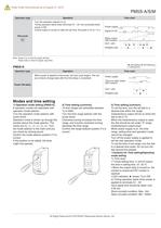
Partly Order Discontinued as of August 31, 2012 Operation type Time chart Turn the operation selector to [ocj. Timing operation starts when terminals A1 - B1 are connected while Control output is turned on after the set time, the pulse is 0.5 to 1.0 s. Power supply Relay output Note: Keep 0.1s or more for power off time. Keep 0.05s or more for signal, input time. Operation type Time chart When power is applied continuously, the time cycle begins. The out- put contacts change state after the time delay is completed. Power ON-delay Power supply Time-out relay output Modes and time setting 1)...
Open the catalog to page 5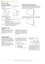
Partly Order Discontinued as of August 31, 2012 The inputs of the PM5S-A/M are voltage (voltage imposition or open) inputs. The PM5S should be mounted as horizontally as possible. When mounting the PM5S on a socket mounting track, hook portion (A) of the Timer to an edge of the track first, and then depress the Timer in the direction of (B). No-contact input (Connection to PNP output sensor.) Contact input Operates with transistor ON Operates with relay ON Voltage Input Signal Levels No-contact input Contact input 1. Transistor ON Residual voltage: 1 V max. (Voltage between terminals B1 and...
Open the catalog to page 6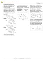
Partly Order Discontinued as of August 31, 2012 Contact or transistor for external input signal A1 B1 Power supply Operating voltage Surge voltage Surge wave form [±(1.2×50)µs single polarity full wave voltage] 3. For connecting and disconnecting operating voltage to the timer, a circuit should be used to prevent the flow of leakage current. For example, a circuit for contact protection as shown in Fig. C will permit leakage current to flow through R and C, causing erroneous operation of the timer. Instead, the circuit shown in Fig. D should be used. No good Leak current Crest value Power...
Open the catalog to page 7All Panasonic Electric Works Corporation of America catalogs and technical brochures
-
 SP-Cap
32 Pages
-
 TQC series
7 Pages
-
 ZF-A series
9 Pages
-
 EEH-ZE Series
9 Pages
-
 ZC-A series
9 Pages
-
 EEH-AZA1E151B
9 Pages
-
 PAN1780‑AT
37 Pages
-
 LD-P RELAYS
8 Pages
-
 ERJH2CF1R33X
7 Pages
-
 R35K (0.35 mm pitch
10 Pages
-
 ZKU series
9 Pages
-
 LQ RELAYS
9 Pages
-
 SF-M RELAYS
8 Pages
-
 PhotoMOS HF
14 Pages
-
 ZU series
9 Pages
-
 ZSU series
9 Pages
-
 ZSU-A series
9 Pages
-
 PAN1781
23 Pages
-
 PAN9520 ETU
35 Pages
-
 PAN9520
36 Pages
-
 Energy Solutions
15 Pages
-
 Line Card Catalog
68 Pages
-
 HE-V RELAYS
5 Pages
-
 PAN1026A
2 Pages
-
 Light touch switch
14 Pages
-
 ETQ Series Power Choke CoiLs
1 Pages
-
 DP3 Catalog
14 Pages
-
 AQY DIP Flat Package Catalog
4 Pages
-
 AQW DIP 2 Form A Catalog
4 Pages
-
 AQV SOP Form B Catalog
4 Pages
-
 AQ-K Catalog
3 Pages
-
 AQ-F Catalog
5 Pages
-
 ABS Catalog
11 Pages
-
 A4F Catalog
9 Pages
-
 EX-L200 series
12 Pages
-
 LP-400 series
16 Pages
-
 HL-G1 Series
16 Pages
-
 D-Imager Catalog
2 Pages
-
 A35S Catalog
8 Pages
-
 a4-catalog
175 Pages
-
 e-catalog
81 Pages
-
 lighting-relays-catalog
6 Pages
-
 kw-catalog
28 Pages
-
 th-meter-catalog
18 Pages
-
 lh2h-catalog
8 Pages
-
 kt-catalog
16 Pages
-
 hl-azh-catalog
15 Pages
-
 ql-az4-catalog
6 Pages
-
 vl-az8-catalog
8 Pages
-
 lt4h-catalog
16 Pages
-
 pmh-catalog
7 Pages
-
 pv310-catalog
12 Pages
-
 lightpix-ae20-catalog
8 Pages
-
 S1DXM
S1DXM30 Pages
-
 SF4B-G
6 Pages
-
 TH (Sensor)
16 Pages
-
 UJ20
UJ2011 Pages
-
 VL-T
VL-T19 Pages
-
 LightPix AE20
8 Pages
-
 LP-S500W
12 Pages
-
 HL (AZH)
30 Pages
-
 GT21C
GT21C24 Pages
-
 FX-500
20 Pages
-
 FM-200
12 Pages
-
 EQ-500
12 Pages
-
 DPC-DPH 100
22 Pages
-
 DL (AZD1)
23 Pages
-
 Lighting
43 Pages
-
 AX40
AX4012 Pages
-
 VIC100
6 Pages
-
 Programmable Controller FP2
20 Pages
-
 FPSIGMA Programmable Controller
20 Pages
-
 CX-400 Version 2
24 Pages
-
 KW Catalog
17 Pages
-
 LH2H Catalog
29 Pages
-
 LCH Catalog
34 Pages
-
 KT Catalog
20 Pages
-
 AZ5 Catalog
22 Pages
-
 LT4H Catalog
39 Pages
-
 A100/200 Catalog
26 Pages
-
 UJ30/35 Catalog
12 Pages
-
 LP-F10 Catalog
4 Pages
-
 LP-200 Catalog
6 Pages
-
 NA1-11 Catalog
8 Pages
-
 GN Catalog
10 Pages
-
 Data Logger Light Catalog
4 Pages


