Catalog excerpts
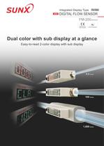
Integrated Display Type For Gas DIGITAL FLOW SENSOR FM-200 SERIES Ro Conforming to EMC Directive RoHS Compatible Dual color with sub display at a glance Easy-to-read 2-color display with sub display 0.5 ℓ/min. 100 ℓ/min. 1,000 ℓ/min.
Open the catalog to page 1
Easy-to-see dual color with sub display! The setting conditions are displayed on the sub display, making it much easier to keep track of operations. In addition, the digital display which switches between 2 colors lets you check the status of sensor operation at a glance. Easy to see with the sub display! Dual color display at a glance ■_<a«?y iw ^v*u vii«?|si«y . The display color changes in accordance Setting values and setting items can be checked at the same time. with output ON / OFF operations. Main display | | Sub display] Setting value Setting item -1 Main display | | Sub display!...
Open the catalog to page 2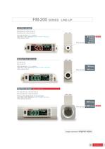
FM-200 SERIES LINE-UP Low flow rate type FM-252-4(-P) / FM-213-4(-P) FM-253-4(-P) / FM-214-4(-P) ●Port size: ø4 mm ø0.157 in push-in ●Size: W17 × H37 × D64 mm W0.669 × H1.457 × D2.520 in ●Body material: Resin ■ Flow rate range 0.5 ℓ/min. 1 ℓ/min. 5 ℓ/min. 10 ℓ/min. Smallest Type Medium flow rate type FM-254-8(-P) FM-215-8(-P) ●Port size: ø8 mm ø0.315 in push-in ●Size: W17 × H43 × D70.6 mm W0.669 × H1.693 × D2.780 in ●Body material: Resin High flow rate type 50 ℓ/min. ■ Flow rate range 100 ℓ/min. Industry’s smallest in size (Based on research conducted by SUNX as of March 2008)...
Open the catalog to page 3
Suitable for cost and quality control! Integrated output mode incorporated The FM-200 series can control and manage flows in a wide variety of output modes such as integrated output mode, depending on the required application. Integrated flow rate display Integrated output mode When the volume of flow of the gas being measured reaches the set integrated value, output switches to ON or OFF. Integrated flow rate Quality control ●Controls N2 charging volumes for electronic components ●Controls air blowing volumes, etc. Integrated flow value 0 Time ON Comparative output OFF ON Comparative...
Open the catalog to page 4
Applications Controlling purge gas and air blowing Checking seating Checking suction By controlling purge gas and air blowing, performance and quality of the products can be maintained, while contributing to cost reduction. Flow sensors can be used for stable detection of transparent objects which were difficult to detect using photoelectric sensors. The nozzle can be extended for detection even in places where oil spatter occurs. Detection of objects is possible even on conveyors with low suction pressures where air is flowing constantly (such as collet conveyors and network conveyors)....
Open the catalog to page 5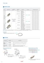
FM-200 ORDER GUIDE Type Appearance Applicable uid Flow rate range Model No. 500 mℓ/min. Resin body type 1,000 mℓ/min. 5 ℓ/min. 10 ℓ/min. Clean air (Note) Compressed air (Note) Nitrogen gas 50 ℓ/min. 100 ℓ/min. Port size Comparative output FM-252-4 NPN Open-collector transistor FM-252-4-P PNP Open-collector transistor FM-213-4 NPN Open-collector transistor FM-213-4-P FM-253-4 PNP Open-collector transistor ø4 ø0.157 push-in NPN Open-collector transistor FM-253-4-P PNP Open-collector transistor FM-214-4 NPN Open-collector transistor FM-214-4-P PNP Open-collector transistor FM-254-8 NPN...
Open the catalog to page 6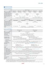
FM-200 SPECIFICATIONS Individual specications Type Item Model No. Resin body type FM-252-4(-P) FM-213-4(-P) FM-253-4(-P) FM-214-4(-P) Integrated Instant ow rate ow rate Full scale ow rate (Note 1) 500 mℓ/min. 1,000 mℓ/min. 5 ℓ/min. 10 ℓ/min. Display range (Note 2) –550 to +550 mℓ/min. –1,100 to +1,100 mℓ/min. –5.5 to +5.5 ℓ/min. –11 to +11 ℓ/min. Setting and display resolution 1 mℓ/min. 0.01 ℓ/min. Display range (Note 2) ±9999999 mℓ ±99999.99 ℓ Setting and display resolution 1 mℓ 0.01 ℓ Specied integrated value 5 mℓ 10 mℓ 0.05 ℓ 0.1 ℓ Port size ø4 ø0.157 push-in Weight Net weight: 50 g...
Open the catalog to page 7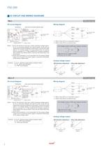
FM-200 I/O CIRCUIT AND WIRING DIAGRAMS FM-2□ NPN output type I/O circuit diagram Wiring diagram Color code of connector attached cable Terminal No. Main circuit D1 2 Tr1 D3 Tr3 Brown (Brown) +V 1 (Black) CH1 D2 (Comparative output 1) Load D4 3 Tr2 1 kΩ approx. Varistor (Note 1) Load Load Load * 1 50 mA max. (White) CH2 (Comparative output 2 / External input) 50 mA max. 4 (Gray) Analog voltage output (Note 2) 5 (Blue) 0 V Internal circuit Black *1 + White + - 12 to 24 V DC ± 10 % - 12 to 24 V DC ± 10 % *2 Gray *2 Blue * 1: When using CH2 as a comparative output 2 * 2: When using CH2 as an...
Open the catalog to page 8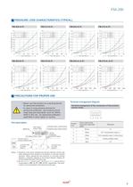
FM-200 PRESSURE LOSS CHARACTERISTICS (TYPICAL) FM-213-4(-P) 0.07 0.06 0.05 0.04 0.03 0.02 0.01 0.1 0.2 0.3 0.4 Flow rate (ℓ/min.) 0.5 0.10 0.08 0.06 0.04 0 0.2 0.4 0.6 0.8 Flow rate (ℓ/min.) 1.0 Pressure loss (kPa) 5 4 3 2 1 20 30 40 Flow rate (ℓ/min.) 50 6 0.6 0.4 4 3 2 3.0 2.5 2.0 1.5 1.0 0.5 1 2 3 4 Flow rate (ℓ/min.) 5 0 40 60 80 Flow rate (ℓ/min.) 100 4 6 8 Flow rate (ℓ/min.) 10 40 0.3 MPa 0.5 MPa 0.7 MPa 35 8 6 4 30 25 20 15 10 2 20 2 FM-216-A□2(-P) 0.3 MPa 0.5 MPa 0.7 MPa 10 5 0 0.8 12 1 10 3.5 FM-255-A□2(-P) 0.1 MPa 0.3 MPa 0.5 MPa 7 0.1 MPa 0.3 MPa 0.5 MPa 4.0 1.0 0 8 0.1 MPa 0.3...
Open the catalog to page 9
FM-200 PRECAUTIONS FOR PROPER USE Mounting • This product can be installed facing up or down or to the left or right. Horizontal mounting • Use M3 screws, and the tightening torque should be 0.5 N·m. • Install a filter, an air dryer and an oil mist filter (microalescer) onto the primary side (upstream) of this product since the compressed air from the compressor contains drain (water, oil oxide and foreign materials, etc.). Mesh (wire net) in this product is used to rectify the flow in the pipe. Always install a lter to the primary side of this product since this mesh is not a lter to...
Open the catalog to page 10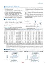
FM-200 PRECAUTIONS FOR PROPER USE • Take care if foreign materials are mixed in the sensing part, the product may break. • Do not use this product for commercial purposes since the product does not comply with International System of Units (SI). • Do not apply pressure that exceed resistant-pressure. • Do not use during the initial transient time (approx. 5 sec.) after the power supply is switched ON. • The specifications may not be satisfied in a strong magnetic eld. • Accuracy of the display and the analog voltage output is inuenced by self-heating by applying current other than the...
Open the catalog to page 11All Panasonic Electric Works Corporation of America catalogs and technical brochures
-
SP-Cap
32 Pages
-
TQC series
7 Pages
-
ZF-A series
9 Pages
-
EEH-ZE Series
9 Pages
-
ZC-A series
9 Pages
-
EEH-AZA1E151B
9 Pages
-
PAN1780‑AT
37 Pages
-
LD-P RELAYS
8 Pages
-
ERJH2CF1R33X
7 Pages
-
R35K (0.35 mm pitch
10 Pages
-
ZKU series
9 Pages
-
LQ RELAYS
9 Pages
-
SF-M RELAYS
8 Pages
-
PhotoMOS HF
14 Pages
-
ZU series
9 Pages
-
ZSU series
9 Pages
-
ZSU-A series
9 Pages
-
PAN1781
23 Pages
-
PAN9520 ETU
35 Pages
-
PAN9520
36 Pages
-
Energy Solutions
15 Pages
-
Line Card Catalog
68 Pages
-
HE-V RELAYS
5 Pages
-
PAN1026A
2 Pages
-
Light touch switch
14 Pages
-
ETQ Series Power Choke CoiLs
1 Pages
-
DP3 Catalog
14 Pages
-
AQY DIP Flat Package Catalog
4 Pages
-
AQW DIP 2 Form A Catalog
4 Pages
-
AQV SOP Form B Catalog
4 Pages
-
AQ-K Catalog
3 Pages
-
AQ-F Catalog
5 Pages
-
ABS Catalog
11 Pages
-
A4F Catalog
9 Pages
-
EX-L200 series
12 Pages
-
LP-400 series
16 Pages
-
HL-G1 Series
16 Pages
-
D-Imager Catalog
2 Pages
-
A35S Catalog
8 Pages
-
a4-catalog
175 Pages
-
e-catalog
81 Pages
-
lighting-relays-catalog
6 Pages
-
kw-catalog
28 Pages
-
th-meter-catalog
18 Pages
-
lh2h-catalog
8 Pages
-
kt-catalog
16 Pages
-
hl-azh-catalog
15 Pages
-
ql-az4-catalog
6 Pages
-
vl-az8-catalog
8 Pages
-
lt4h-catalog
16 Pages
-
pm5s-catalog
7 Pages
-
pmh-catalog
7 Pages
-
pv310-catalog
12 Pages
-
lightpix-ae20-catalog
8 Pages
-
S1DXM
30 Pages
-
SF4B-G
6 Pages
-
TH (Sensor)
16 Pages
-
UJ20
11 Pages
-
VL-T
19 Pages
-
LightPix AE20
8 Pages
-
LP-S500W
12 Pages
-
HL (AZH)
30 Pages
-
GT21C
24 Pages
-
FX-500
20 Pages
-
EQ-500
12 Pages
-
DPC-DPH 100
22 Pages
-
DL (AZD1)
23 Pages
-
Lighting
43 Pages
-
AX40
12 Pages
-
VIC100
6 Pages
-
Programmable Controller FP2
20 Pages
-
FPSIGMA Programmable Controller
20 Pages
-
CX-400 Version 2
24 Pages
-
KW Catalog
17 Pages
-
LH2H Catalog
29 Pages
-
LCH Catalog
34 Pages
-
KT Catalog
20 Pages
-
AZ5 Catalog
22 Pages
-
LT4H Catalog
39 Pages
-
A100/200 Catalog
26 Pages
-
UJ30/35 Catalog
12 Pages
-
LP-F10 Catalog
4 Pages
-
LP-200 Catalog
6 Pages
-
NA1-11 Catalog
8 Pages
-
GN Catalog
10 Pages
-
Data Logger Light Catalog
4 Pages


