Catalog excerpts
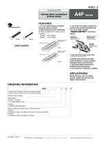
Narrow pitch connectors (0.4mm pitch) 3. Low prole and highly resistant to various environments possible with the use of highly reliable “ ” connector design. 1. 0.6 mm mated height low prole two-piece type connector 2. Space-saving (3.0 mm widthwise) Smaller compared to F4 series (40 pin contacts): Socket — 40% smaller, Header — 43% smaller Bellows contact construction (Against solder rise!) (Against dropping!) Soldering terminals at each corner Suction face: 0.8mm Porosity treatment (Against corrosive gases!) Soldering terminals at each corner Suction face: 1.1mm V notch and Double contact constructions (Against foreign particles and flux!) 4. Simple lock structure provides tactile feedback to ensure excellent mating/unmating operation feel. 5. Gull-wing-shaped terminals to facilitate visual inspections. 6. Connectors for inspection available APPLICATIONS Mobile devices, such as cellular phones, digital still cameras and digital video cameras. 3: Narrow Pitch Connector A4F (0.4 mm pitch) Socket 4: Narrow Pitch Connector A4F (0.4 mm pitch) Header Number of pins (2 digits) Mated height / 1: For mated height 0.6 mm Functions 2: Without positioning bosses Surface treatment (Contact portion / Terminal portion) 4: Ni plating on base, Au plating on surface (for Ni barrier available) 4: Ni plating on base, Au plating on surface Panasonic Corporation Automation Controls Business Division
Open the catalog to page 1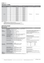
AXE3, 4 PRODUCT TYPES Mated height Part number Outer carton Notes: 1. Order unit: For volume production: 1-inner carton (1-reel) units Samples for mounting check: 50-connector units. Please contact our sales ofce. Samples: Small lot orders are possible. Please contact our sales ofce. 2. Please contact us for connectors having a number of pins other than those listed above. SPECIFICATIONS Ⅵ Characteristics Item Rated current Rated voltage Contact resistance Mechanical characteristics Breakdown voltage Insulation resistance Electrical characteristics Specications 0.3A/pin contact (Max. 5 A at...
Open the catalog to page 2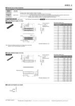
AXE3, 4 Ⅵ Material and surface treatment Part name Molded portion Contact and Post Surface treatment — Copper alloy Contact portion: Base: Ni plating Surface: Au plating Terminal portion: Base: Ni plating Surface: Au plating (except the terminal tips) The socket terminals close to the portion to be soldered have nickel barriers (exposed nickel portions). Soldering terminals: Sockets: Base: Ni plating Surface: Pd+Au ash plating (except the terminal tips) Headers: Base: Ni plating Surface: Au plating (except the terminal tips) The CAD data of the products with a mark can be downloaded from:...
Open the catalog to page 3
AXE3, 4 EMBOSSED TAPE DIMENSIONS (Unit: mm) (Common for respective contact types, sockets and headers) Ⅵ Specications for taping (In accordance with JIS C 0806-3:1999. However, not applied to the mounting-hole pitch of some connectors.) Ⅵ Specications for the plastic reel (In accordance with EIAJ ET-7200B.) Taping reel Leading direction after packaging Embossed carrier tape Embossed mounting-hole Ⅵ Dimension table (Unit: mm) Type/Mated height Common for sockets and headers 0.6 mm Ⅵ Connector orientation with respect to embossed tape feeding direction Type Common for A4F Direction of tape...
Open the catalog to page 4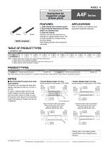
Connectors for inspection usage (0.4mm pitch) RoHS compliant 1. 3,000 mating and unmating cycles 2. Same external dimensions and foot pattern as standard type. 3. Improved mating Insertion and removal easy due to a reduction in mating retention force. This is made possible by a simple locking structure design. Note: Mating retention force cannot be warranted. Ideal for module unit inspection and equipment assembly inspection TABLE OF PRODUCT TYPES ✩: Available for sale Product name 10 ✩ Notes: 1. Please inquire about number of pins other than those shown above. 2. Please inquire with us...
Open the catalog to page 5
Notes on Using Narrow pitch Connectors Notes on Using Narrow pitch Connectors Regarding the design of devices and PC board patterns 1) When connecting several connectors together by stacking, make sure to maintain proper accuracy in the design of structure and mounting equipment so that the connectors are not subjected to twisting and torsional forces. 2) With mounting equipment, there may be up to a ±0.2 to 0.3-mm error in positioning. Be sure to design PC boards and patterns while taking into consideration the performance and abilities of the required equipment. 3) Some connectors have...
Open the catalog to page 6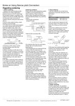
Notes on Using Narrow pitch Connectors Regarding soldering Soldering conditions Please use the reow temperature prole conditions recommended below for reow soldering. Please contact us before using a temperature prole other than that described below (e.g. lead-free solder). • Narrow pitch connectors (except P8 type) Upper limited (Solder heat resistance) Lower limited (Solder wettability) Temperature Peak temperature 260°C 230°C 180°C 150°C 4) Consult us when using a screenprinting thickness other than that recommended. 5) When mounting on both sides of the PC board and the connector is...
Open the catalog to page 7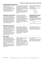
Notes on Using Narrow pitch Connectors Handling Single Components 1) Make sure not to drop or allow parts to fall from work bench 2) Excessive force applied to the terminals could cause warping, come out, or weaken the adhesive strength of the solder. Handle with care. 3) Repeated bending of the terminals may cause terminals to break. 4) Do not insert or remove the connector when it is not soldered. Forcibly applied external pressure on the terminals can weaken the adherence of the terminals to the molded part or cause the terminals to lose their evenness. 5) Excessive prying-force applied...
Open the catalog to page 8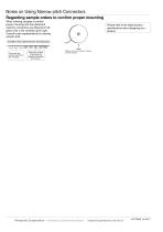
Notes on Using Narrow pitch Connectors Regarding sample orders to conrm proper mounting When ordering samples to conrm proper mounting with the placement machine, connectors are delivered in 50piece units in the condition given right. Consult a sale representative for ordering sample units. Please refer to the latest product specications when designing your product. Condition when delivered from manufacturing Reel Embossed tape amount required for the mounting Required number of products for sample production (Delivery can also be made on a reel by customer request.) Panasonic Corporation...
Open the catalog to page 9All Panasonic Electric Works Corporation of America catalogs and technical brochures
-
SP-Cap
32 Pages
-
TQC series
7 Pages
-
ZF-A series
9 Pages
-
EEH-ZE Series
9 Pages
-
ZC-A series
9 Pages
-
EEH-AZA1E151B
9 Pages
-
PAN1780‑AT
37 Pages
-
LD-P RELAYS
8 Pages
-
ERJH2CF1R33X
7 Pages
-
R35K (0.35 mm pitch
10 Pages
-
ZKU series
9 Pages
-
LQ RELAYS
9 Pages
-
SF-M RELAYS
8 Pages
-
PhotoMOS HF
14 Pages
-
ZU series
9 Pages
-
ZSU series
9 Pages
-
ZSU-A series
9 Pages
-
PAN1781
23 Pages
-
PAN9520 ETU
35 Pages
-
PAN9520
36 Pages
-
Energy Solutions
15 Pages
-
Line Card Catalog
68 Pages
-
HE-V RELAYS
5 Pages
-
PAN1026A
2 Pages
-
Light touch switch
14 Pages
-
ETQ Series Power Choke CoiLs
1 Pages
-
DP3 Catalog
14 Pages
-
AQY DIP Flat Package Catalog
4 Pages
-
AQW DIP 2 Form A Catalog
4 Pages
-
AQV SOP Form B Catalog
4 Pages
-
AQ-K Catalog
3 Pages
-
AQ-F Catalog
5 Pages
-
ABS Catalog
11 Pages
-
EX-L200 series
12 Pages
-
LP-400 series
16 Pages
-
HL-G1 Series
16 Pages
-
D-Imager Catalog
2 Pages
-
A35S Catalog
8 Pages
-
a4-catalog
175 Pages
-
e-catalog
81 Pages
-
lighting-relays-catalog
6 Pages
-
kw-catalog
28 Pages
-
th-meter-catalog
18 Pages
-
lh2h-catalog
8 Pages
-
kt-catalog
16 Pages
-
hl-azh-catalog
15 Pages
-
ql-az4-catalog
6 Pages
-
vl-az8-catalog
8 Pages
-
lt4h-catalog
16 Pages
-
pm5s-catalog
7 Pages
-
pmh-catalog
7 Pages
-
pv310-catalog
12 Pages
-
lightpix-ae20-catalog
8 Pages
-
S1DXM
30 Pages
-
SF4B-G
6 Pages
-
TH (Sensor)
16 Pages
-
UJ20
11 Pages
-
VL-T
19 Pages
-
LightPix AE20
8 Pages
-
LP-S500W
12 Pages
-
HL (AZH)
30 Pages
-
GT21C
24 Pages
-
FX-500
20 Pages
-
FM-200
12 Pages
-
EQ-500
12 Pages
-
DPC-DPH 100
22 Pages
-
DL (AZD1)
23 Pages
-
Lighting
43 Pages
-
AX40
12 Pages
-
VIC100
6 Pages
-
Programmable Controller FP2
20 Pages
-
FPSIGMA Programmable Controller
20 Pages
-
CX-400 Version 2
24 Pages
-
KW Catalog
17 Pages
-
LH2H Catalog
29 Pages
-
LCH Catalog
34 Pages
-
KT Catalog
20 Pages
-
AZ5 Catalog
22 Pages
-
LT4H Catalog
39 Pages
-
A100/200 Catalog
26 Pages
-
UJ30/35 Catalog
12 Pages
-
LP-F10 Catalog
4 Pages
-
LP-200 Catalog
6 Pages
-
NA1-11 Catalog
8 Pages
-
GN Catalog
10 Pages
-
Data Logger Light Catalog
4 Pages


