- Catalogs
- ORIENTAL MOTOR
- DSC Series
- Products
- Catalogs
- News & Trends
- Exhibitions
DSC Series
1 /76Pages

DSC Series
1 /76Pages
Catalog excerpts

AC Speed Control Motors DSC Series Simple to use Speed Control with Closed Loop Performance.
Open the catalog to page 1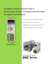
A Speed Control Solution that is Reasonably Priced, Compact and Provides Excellent Performance. Speed Controllers Providing an answer to the call for the ability to change speed without the hassle of changing settings, the DSC Series provides easy, intuitive functions that don't require laborious adjustment, even for first time users. Actual Size AC Speed Control Motors
Open the catalog to page 2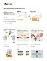
■Features Speed Control Using Closed Loop Control Speed regulation ±1% (Reference value) Speed is always monitored by the tachogenerator built into the AC motor. The actual speed is controlled to match the speed setting, even when the load fluctuates. DSC Series Digital Circuit (Block diagram) Digital Circuits Most of the analog circuits that were used in the past have been digitized, now run by the CPU, and circuit components have been vastly reduced. This has reduced the size as well as the number of circuit components. Due to this, it is possible to make the deviation for the speed command...
Open the catalog to page 3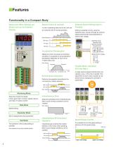
■Features Functionality in a Compact Body Speed and Other Settings are Shown and can be Entered Directly Speed Control (4 speeds) 4 units of operating data can be set, and can be switched with I/O during operation. No.3 No.2 No.1 No.0 External Speed Setting Input is Possible Setting is possible not only using the operation keys, but also through an external speed potentiometer (sold separately) or external DC voltage. Motor Movement ①Setting Using Operation Key ②External Speed Potentiometer Peripheral Equipment (Sold separately) External Speed Remote Setting Makes the motor movement at start/stop...
Open the catalog to page 4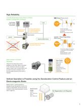
High Reliability Low Electrical Noise Gives Peace of Mind, System Configuration is Simple Circuit Breaker or Earth Leakage Circuit Breaker DSC Series [Phase control] Voltage Short Circuit Shutdown Controls the voltage 1 cycle performs 2 switchings [Conditions] ●Power supply frequency: 60 Hz Overload Protection Overheat Protection Output Available Speed Controller Inverter + Three-Phase Motor Capacitor Sensors and Other Devices Circuit Protector Thermal Protector Provides Overheat Protection Solid State Relay Controls the voltage and frequency 1 cycle performs 300 switchings [Condition] ●Carrier...
Open the catalog to page 5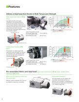
■Features Utilizes a Gearhead that Excels in Both Torque and Strength Uses high-strength hypoid gears. Compared to conventional products, torque has been greatly increased and noise has been reduced. Furthermore, the radial load and axial load on the gearhead output shaft have been increased, contributing to decreased equipment size and increased reliability. Permissible Radial Load Rated Torque [lb-in] Right-angle Shaft Hypoid JH/JL Gears 50 40 Rated Torque 2.7 Times Higher DSC Series 90 W Permissible Torque Conventional Product 5GE-RH 90 W Output Power 90 W (1/8 HP) Permissible Radial Load...
Open the catalog to page 6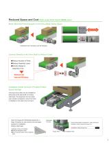
Reduced Space and Cost Right-angle Shaft Hypoid JH/JL Gears Motor Mounted Perpendicularly to the Drive Shaft, Saves Space Space Saving Extension from conveyor can be reduced. Connect Directly to the Drive Shaft to Reduce Costs ●Reduce Number of Parts ●Reduce Assembly Labor ●Shorten Design & Assembly Time Reduced Cost Improved Efficiency Installation Inside Conveyor Provides Further Space Savings Conveyor drive rollers can be installed on both ends of the load shaft of a hollow shaft type. The equipment can be made even smaller compared to when the motor is installed on the side of the conveyor....
Open the catalog to page 7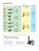
Speed Controller Connection Cable Power Supply Voltage [V] Single-phase 100 VAC Single-phase 110/115 VAC Single-phase 200 VAC Single-phase 220/230 VAC Standard Type Round Shaft Type 4 Page 26 Single-phase 100 VAC Single-phase 110/115 VAC Single-phase 200 VAC Single-phase 220/230 VAC Single-phase 100 VAC Single-phase 110/115 VAC Single-phase 200 VAC Single-phase 220/230 VAC Single-phase 100 VAC Single-phase 110/115 VAC Single-phase 200 VAC Single-phase 220/230 VAC Max. Permissible Torque [N-m (lb-in)] Cable Type Connection Cables Flexible Connection Cables Connection Cables Flexible Connection...
Open the catalog to page 8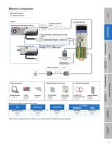
©Purchase is required OPurchase as necessary DC Power Supply Cable To be supplied by customer ^ Page 73 O Connection Cable / Flexible Connection Cable ^ Page 72 Maximum Extension Length: 10.5 m (34.4 ft.) (Including 0.5 m (1.6 ft.) Motor Cable) ® Speed Controller OCables for I/O Signals ^ Page 73 Host Control Device O Motor Accessories Mounting Brackets Flexible Torque Arms ^ Page 75 Speed Controller Accessories Driver Mounting Brackets ^ Page 74 External Speed Potentiometer ^ Page 75 Capacitor Accessories Lead Wires for Capacitor Connection ^ Page 72 Capacitor Mounting Brackets ^ Page 74 •Example...
Open the catalog to page 9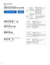
Motor Product Name • Motor O Right-Angle Shaft Hypoid Gearhead Gearhead Product Name O Parallel Shaft Gearhead GV Gear SCM 4 25 UA -15 © © ® © © © O Round Shaft Type SCM 4 25 A-UA © © ® © © • Speed Controller DSCD 25 UA © © ® © • Connection Cable, Flexible Connection Cable CC 01 SC R © © ® © ©
Open the catalog to page 10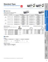
■Product Line • Right-Angle Shaft Hypoid Gearhead Price includes motor and gearhead. Output Power • Speed Controller Price includes speed controller, capacitor and capacitor cap. •Connection Cables • Flexible Connection Cables Output Power ■Included • Motor Shaft Type •Speed Controller Capacitor A number indicating the gear ratio is specified where the box □ is located within the product name.
Open the catalog to page 11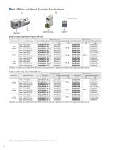
Speed Controller •A capacitor and a capacitor cap are included with the speed controller product (product name @). A capacitor cap is not included with the capacitor product (product name ©). A number indicating the gear ratio is specified where the box □ is located within the product name.
Open the catalog to page 12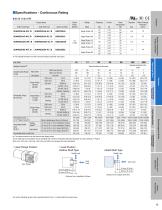
Product Name TP: This indicates that there is a built-in thermal protector (automatic return type). ❖ 1 The rotation direction is as seen from the gear flange surface. ❖ 2 The radial load at each distance can be calculated with a formula. Permissible radial load calculation for hollow shaft type ^ Page 25 • 90 r/min, 1200 r/min, 1400 r/min, 1450 r/min, and 1600 r/min represent the motor shaft speed. O Gear Flange Position O Load Position • Hollow Shaft Type • Solid Shaft Type Radial Load Axial Load Distance from Installation Surface Distance from Output Shaft End A number indicating the gear...
Open the catalog to page 13All ORIENTAL MOTOR catalogs and technical brochures
 Product Guide
36 Pages
 Product Guide
36 Pages
 Linear & Rotary Actuators
11 Pages
 Rack and Pinion System L Series
28 Pages
 DRS series
2 Pages
 DGII
DGII2 Pages
 EH series
12 Pages
 Servo Motors
7 Pages
 Motors Torque
6 Pages
 BLH Series
36 Pages
 Electric CylindersEAC Series
2 Pages
 DSC Series
11 Pages
 Overview of Standard AC Motors
21 Pages
 BLE2 Series Brushless DC Motors
18 Pages
 BMU Series Brushless DC Motors
18 Pages
 Catalog Overview
24 Pages
 BXII Series
31 Pages
 RKII Series
51 Pages
 AZ Series
10 Pages
 CVK Series
24 Pages
 Stepper Motors
33 Pages
 Universal Controller, SCX11
4 Pages
 Standard AC Motors
9 Pages
 Servo motors
9 Pages
 Stepping Motors
23 Pages
 Cooling Module
8 Pages
 KII Series
16 Pages
 RK Series
4 Pages
 AS Series
4 Pages
 AR Series
4 Pages
 Controllers for Stepping Motors
18 Pages
 AC Motor Systems
62 Pages
 VEXTA Brushless DC Motors
60 Pages
 AC Motor Accessories
16 Pages
 Clutch & Brake Motors
8 Pages
 Electromagnetic Brake Motors
44 Pages
 Reversible Motors
36 Pages
 Induction Motors
54 Pages


