
- Catalogs
- ORIENTAL MOTOR
- AC Motor Systems


- Products
- Catalogs
- News & Trends
- Exhibitions
AC Motor Systems

AC Motor Systems
The document provides a comprehensive overview of the BHF Series AC Motor Systems, focusing on speed control systems, specifications, and configurations. It highlights the features, safety standards, and global specifications of the BHF Series motors.
The BHF Series motors are 200 W (1/4 HP) AC speed-control motors with a frame size of 4.09 inches square. They offer excellent speed stability with a fluctuation of only 3% and include an automatic control of an electromagnetic brake. The motors are pre-assembled with a gearhead for easy installation.
- Excellent speed stability with a dedicated inverter.
- Automatic control of electromagnetic brakes.
- Smallest frame size among 200 W motors.
- Wiring length up to 164 feet (50 m).
- Full-range functionality including alarm output and speed monitor output.
- Wide product variations with different shaft types and gear ratios.
- Compliance with international power-supply voltage specifications and safety standards.
The BHF Series conforms to various international standards, including UL, CSA, and CE marking, ensuring compliance with Low Voltage and EMC Directives.
The system includes a combination type pre-assembled gearmotor, inverter, programmable controller, and AC power supply. Accessories such as mounting brackets and flexible couplings are available.
The product line includes various models with different power supply voltages and gear ratios. Models are available with or without electromagnetic brakes.
The motors have insulation resistance of 100 MΩ or more, dielectric strength of 1.5 kV, and a temperature rise of 126°F (70°C) or less. They operate within an ambient temperature range of 14°F to 104°F and have a degree of protection of IP54.
The document details permissible overhung and thrust loads for different shaft types, ensuring the bearing life is not compromised.
The BHF Series AC Motor Systems offer robust and versatile solutions for speed control applications, with a focus on stability, safety, and compliance with international standards.
The document outlines the specifications and characteristics of the BHF Series motors, focusing on continuous duty regions and permissible load inertia. It provides detailed model information, including voltage and gear ratio inputs.
The motors are designed for continuous operation within specified speed and torque ranges. Performance graphs show torque versus speed, highlighting the continuous duty region and gravitational operation capabilities.
For vertical movements, the motors can function as power generators due to external forces. A regeneration unit, such as the EPRC-400P, is recommended to convert regenerative energy into thermal energy.
Details are provided for various motor/gearhead combinations, including right-angle hollow shaft, right-angle solid shaft, and parallel shaft types.
The document includes connection diagrams for single-phase and three-phase power supplies, detailing input/output signal terminals and their functions.
Instructions for mounting loads on hollow shafts are provided, including recommended shaft dimensions and the use of spacers, washers, and retaining rings.
The document highlights features such as built-in speed potentiometers, alarm indicators, and speed monitor outputs.
The document outlines the specifications for a speed control system, including the use of a three-phase 200-230 VAC power supply with a 10% tolerance at 50/60 Hz.
Instructions are provided for connecting the motor and inverter, emphasizing the use of appropriate lead wires and terminals.
The document highlights the importance of separating signal and motor cables from noise-generating equipment or power lines.
For systems with electromagnetic brakes, it is recommended to use separate cables for the brake and motor to minimize delay times.
The document describes the input and output signal circuits, including the use of small capacity relays and electronic input control.
Speed can be controlled using a built-in potentiometer, an external potentiometer, or external DC voltage.
Various model combinations for motors and inverters are listed, including those with and without electromagnetic brakes.
The document confirms compliance with UL, CSA, and EN standards, and mentions the CE Marking in accordance with EMC and low voltage directives.
The ES01/ES02 speed controllers are highlighted for their multi-functionality, ease of use, and compatibility with a wide range of motors.
This document provides detailed specifications and configurations for speed control systems, focusing on brushless DC motor systems with both AC and DC inputs.
The system configuration includes various components such as right-angle gearheads, motor mounting brackets, flexible couplings, and extension cables.
The product number code provides details on motor type, shaft type, output power, motor frame size, and voltage.
Gearheads are sold separately and are available in various models compatible with different motor types.
Motors have built-in thermal protectors, with specifications including temperature rise, dielectric strength, insulation resistance, and degree of protection.
Specifications cover maximum output power, voltage, frequency, speed range, permissible torque, starting torque, current, and power consumption.
The control unit specifications include ambient humidity, temperature range, dielectric strength, insulation resistance, and degree of protection.
When gearheads are attached, the speed range and permissible torque vary based on the gear ratio.
Permissible overhung load, thrust load, and load inertia for gearheads are specified.
There are distinct operational methods between different motor types, with specific instructions for connection and operation.
Motor speed is adjusted using a potentiometer on the control unit.
The motor stops when the RUN/STAND-BY switch is set to STAND-BY.
Instructions are provided for changing the direction of rotation for different motor types.
The document lists various models with their corresponding output power in HP and W.
Model numbers for motor and control unit combinations are provided.
Extension cables are available for remote operation, allowing installation of the motor and control unit up to 15.7 feet apart.
Catalog excerpts
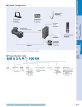
Regeneration Unit(Accessories) ( ➝ Page A-218) Introduction ( ➝ Page A-208) Mounting Bracket(Accessories) ( ➝ Page A-204) BXFBL Programmable Controller (Not Supplied) (Not Supplied) Flexible Coupling(Accessories) Brushless DC Motor Systems Combination Type( Pre-assembled Gearmotor ) 2 AXU AC Power Supply DIN Rail Mounting Plate (Accessories) ( ➝ Page A-217) DC InputAC Input AXH ( ➝ Page A-216) External SpeedPotentiometer (Accessories) BHFESUS BHF Series Inverter AC Motor Systems The system configuration shown is an example. Other configurations are available. > Before Using aSpeed ControlSystem...
Open the catalog to page 3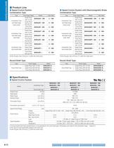
TypeCombination Typewith Right-AngleHollow ShaftCombination Type with Right-AngleSolid ShaftCombination Type with Parallel Shaft Power Supply Voltage Model Gear Ratio TypeCombination Typewith Right-AngleHollow ShaftCombination Typewith Right-AngleSolid ShaftCombination Typewith Parallel Shaft Power Supply Voltage Model Gear Ratio Single-Phase100-115 VACSingle-Phase200-230 VACThree-Phase200-230 VACSingle-Phase100-115 VACSingle-Phase200-230 VACThree-Phase200-230 VACSingle-Phase100-115 VACSingle-Phase200-230 VACThree-Phase200-230 VAC BHF62AT- RHBHF62CT- 5 1805 Single-Phase100-115 VACSingle-Phase200-230...
Open the catalog to page 4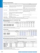
ItemInsulation ResistanceDielectric StrengthTemperature RiseAmbient TemperatureAmbient Humidity Degree of Protection Motor100 M Inverter100 M Ω or more when measured by a 500 VDC megger between thepower supply input terminal and the Protective Earth terminal and between the power supply input terminal and the I/O terminal after continuous operation under normal ambient temperature and humidity. Sufficient to withstand 1.5 kV (3 kV) at 50 Hz and 60 Hz appliedbetween the power supply input terminal and the Protective Earth terminal (between the power supply input terminal and the I/O terminal)...
Open the catalog to page 6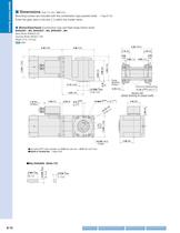
120 1.69 (28.3) 104) ( 1.11 4.09 A'A 0.335 ( 8.5) 2.60 (66) 4 Holes Use cable (VCTF) with a diameter of 0.24 inch ( 6 mm) 0.47 inch ( 12 mm). Details of Terminal Box ➝ Page A-224 >
Open the catalog to page 8
120 1.69 104) ( Before Using aSpeed ControlSystem 4.09 0.335 ( 8.5) 2.60 (66) 4 Holes Use cable (VCTF) with a diameter of 0.24 inch ( 6 mm) 0.47 inch ( 12 mm). Details of Terminal Box ➝ Page A-224 >
Open the catalog to page 9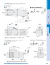
∗ At the time of shipment, a parallel key is inserted on the gearhead's shaft. >
Open the catalog to page 11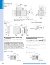
Hollow ShaftSpacer Hollow ShaftSpacerFlat WasherBolt (M6) Load Shaft Flat Washer Load Shaft Bolt (M6) Spring Washer Spring Washer Retaining Ring for Hole Retaining Ring for Hole Spacer
Open the catalog to page 12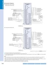
SPEED POWERALARM HL OFF SDSS ONOFFONOFFON SW1 Clockwise rotation /stop selection inputSW2 Counterclockwise rotation /stop selection inputSW3 Speed-setting mode selection input Regeneration unit > ✽ 1 [Accessories (sold separately)] 400 Ω > To TPTo I-COMThermal protector lead wires RG OFF ✽ 2 MB+MB-U ONOFFONONOFF SW4 Slow down inputSW5 Electromagnetic brake release input > B ✽ 2 I-COM ✽ 3 CWCCWMONCNCSDFREERSTTPHML UB SW6 Alarm reset inputRegeneration unitthermal signal input External DC voltage24 VDC0.1 A min. > VW VWLNNCFG Power connection Connect to a single-phase 100-115 VAC FSP200-2 : Connect...
Open the catalog to page 14
Model Motor Gearhead Inverter > Introduction BHF62AT- RA BH6G2- RA FSP200-1 BHF62AT- BH6G2- BHF62CT- RH BH6G2- RH > BXFBL BHF62CT- RA BHM62T-G2 BH6G2- RA FSP200-2 > Brushless DC Motor Systems BHF62CT- BH6G2- BHF62ST- RH BH6G2- RH BHF62ST- RABHF62ST- BH6G2- RABH6G2- FSP200-3 > 2 External potentiometer High speed InverterI/O terminal ● Enter the gear ratio in the box ( ) within the model name. > AXU 1 3 123 321 HML DC InputAC Input Model Motor Inverter > AXH BHF62AT-A FSP200-1 BHF62CT-ABHF62ST-A BHM62T-A FSP200-2FSP200-3 > BHFESUS AC Motor Systems Model Motor Gearhead Inverter BHF62AMT- RH BH6G2-...
Open the catalog to page 17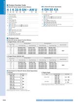
q Motor Frame Size q Gearhead Frame Size Gearhead Type w I : Induction Motor R : Reversible Motor w GN : For use with GN -type pinion shaft motor e K Series GU : For use with GU -type pinion shaft motor e Gear RatioExample r Output Power (W)Example 25 : 25 W 50 : Gear Ratio of 50:1 t Speed Control Motor Type of Bearings and Shaft Type r KA : Ball Bearing Type (inch-size) Motor Shaft Type RAA : Right Angle Solid Shaft Type (inch size) y GN : Pinion Shaft for use with GN -type gearhead RH : Right Angle Hollow Shaft Type GU : Pinion Shaft for use with GU -type gearhead A : Round Shaft Voltage u...
Open the catalog to page 20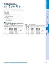
q V Series w Speed Control Motor > Introduction e I : Induction Motor R : Reversible Motor r Motor Frame Size t Output Power (W)Example > BXFBL 25 : 25 W > Brushless DC Motor Systems Voltage y A : Single-Phase 100/110/115 VAC C : Single-Phase 200/220/230 VAC > 2 u Gear RatioExample > 30 : Gear ratio of 30:1 With Capacitor for > AXU i U : Single-Phase 110-115 VAC E : Single-Phase 220-230 VAC > DC InputAC Input AXH BHFESUS Output Power Output Power > AC Motor Systems Induction Motors Reversible Motors Speed Controller1/125 Induction Motors Reversible Motors Speed Controller HP W6 15 25 40 60 90...
Open the catalog to page 21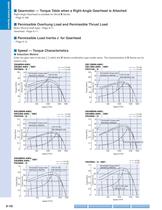
110 VAC115 VAC 110 VAC115 VAC Permissible Torque when Gearhead is Attached 110/115 VACSafe-Operation Line > m] m] Torque [oz-in]Torque [mN Torque [oz-in]Torque [mN 020406080100 0246 8101214 04080120160200240 0510 15 20 253035 150010005001800Speed [r/min] 150010005001800 Speed [r/min] 110/115 VAC Safe-Operation LinePermissible Torque when Gearhead is Attached > 110 VAC115 VAC 110 VAC 115 VAC Permissible Torque when Gearhead is Attached110/115 VAC Safe-Operation Line > m] m] Torque [oz-in]Torque [N Torque [oz-in]Torque [N 110/115 VAC Safe-Operation Line 00.10.20.3 0.40.5 010 203040 506070 00.10.20.3...
Open the catalog to page 32
230 VAC 60 Hz 220 VAC 50 Hz 220 VAC 50 Hz 220 VAC 60 Hz 220 VAC 60 Hz Permissible Torque when Gearhead is Attached 60 HzSafe-Operation Line 60 HzSafe-Operation LinePermissible Torque when Gearhead is Attached > m] m] Introduction Torque [oz-in]Torque [mN Torque [oz-in]Torque [mN 50 Hz Safe-Operation Line > BXFBL 50 Hz Safe-Operation Line > Brushless DC Motor Systems 0204060 80100 02 4 6810 12 14 04080120 160200 051015 2025 150010005001800Speed [r/min] 150010005001800Speed [r/min] > 2 230 VAC 50 Hz 230 VAC 50 Hz > 230 VAC 60 Hz 220 VAC 50 Hz 220 VAC 50 Hz > AXU 220 VAC 60 Hz 220 VAC 60 Hz Permissible...
Open the catalog to page 33All ORIENTAL MOTOR catalogs and technical brochures
 Product Guide
36 Pages
 Product Guide
36 Pages
 Linear & Rotary Actuators
11 Pages
 Rack and Pinion System L Series
28 Pages
 DRS series
2 Pages
 DGII
DGII2 Pages
 EH series
12 Pages
 Servo Motors
7 Pages
 DSC Series
76 Pages
 Motors Torque
6 Pages
 BLH Series
36 Pages
 Electric CylindersEAC Series
2 Pages
 DSC Series
11 Pages
 Overview of Standard AC Motors
21 Pages
 BLE2 Series Brushless DC Motors
18 Pages
 BMU Series Brushless DC Motors
18 Pages
 Catalog Overview
24 Pages
 BXII Series
31 Pages
 RKII Series
51 Pages
 AZ Series
10 Pages
 CVK Series
24 Pages
 Stepper Motors
33 Pages
 Universal Controller, SCX11
4 Pages
 Standard AC Motors
9 Pages
 Servo motors
9 Pages
 Stepping Motors
23 Pages
 Cooling Module
8 Pages
 KII Series
16 Pages
 RK Series
4 Pages
 AS Series
4 Pages
 AR Series
4 Pages
 Controllers for Stepping Motors
18 Pages
 VEXTA Brushless DC Motors
60 Pages
 AC Motor Accessories
16 Pages
 Clutch & Brake Motors
8 Pages
 Electromagnetic Brake Motors
44 Pages
 Reversible Motors
36 Pages
 Induction Motors
54 Pages


