
- Catalogs
- ORIENTAL MOTOR
- AC Motor Accessories


- Products
- Catalogs
- News & Trends
- Exhibitions
AC Motor Accessories

AC Motor Accessories
Overview
This document provides comprehensive technical specifications and guidelines for standard AC motors and their accessories, including various motor types, mounting hardware, couplings, speed indicators, and protective units.
1. Introduction and General Information
Introduces product categories and general technical references essential for selecting and using standard AC motors and accessories.
2. Motor and Gearhead Mounting Brackets
Details eleven aluminum mounting bracket types compatible with motor frames from 42 mm to 104 mm and specific motor models (e.g., SOL0U04, SOL2U08). Brackets include tapped holes for screw mounting but are incompatible with right-angle gearheads, certain watertight motors, and specific gearhead models (5GC-KA, 5GCH-KA). Dimensional drawings and mounting hole specifications are provided, including screw types and bracket weights.
3. Torque Arm
Describes the torque arm as an anti-rotation device for right-angle hollow-shaft gearheads mounted on shafts. It must be firmly secured with M10 or 3/8-16 UNC screws to prevent gearhead rotation. Applicable to BH and BHF series gearheads, with detailed mounting instructions and dimensions.
4. Flexible Couplings
Clamp-type aluminum alloy couplings connect motor shafts to driven equipment shafts. Features include oil resistance, electrical insulation, non-damaging clamping, and easy installation/removal due to separate hub and sleeve design. Emphasizes precise shaft alignment to avoid vibration and premature failure, recommending misalignment below one-third of permissible values. Safety notes stress using specified screws, avoiding finger contact during operation, and ensuring power is off during installation.
A detailed table lists tightening torques for coupling screws by model (MCL20 to MCL65). Guidance is provided for selecting couplings based on shaft diameters and load conditions (regular or shock load).
5. Coupling Product Codes and Compatibility
Explains coupling model codes indicating outer diameter, inner diameters for connected shafts, and type. Compatibility tables link coupling sizes to motor and gearhead models, shaft diameters, and load types.
6. Specifications Summary
Key coupling specifications include outer diameter, length, shaft hole diameters, and nominal torque ratings ranging from 5 N·m (44 lb-in) to 160 N·m (1410 lb-in), with corresponding dimensions.
7. Mechanical Specifications and Dimensions
Provides detailed mechanical data for motor models, including weights, moments of inertia, permissible eccentricity (up to 0.15 mm), declination (1.0°), and end play limits (0.8 mm to 1.5 mm). Shaft hole diameters and tolerances are specified for frame sizes F03 to F12, with clamp and set screw sizes and placements detailed for secure mounting.
8. Motor Model Types and Mounting Details
Lists motor types (MCL20, MCL30, MCL40, MCL55, MCL65) with mechanical dimensions and mounting hardware specifications. Includes scale drawings showing mounting hole locations, shaft dimensions, and screw sizes. Describes mounting plates and adapters for DIN rail installation to facilitate integration of speed control packs and drivers.
9. Speed Indicator (Model SDM496)
Details the SDM496 digital speed indicator for displaying motor or gearhead output shaft speed. Operates on 100-240 VAC, 50/60 Hz. Includes mounting accessories (flush mounting adapter EPUA-31, round socket EP11MS). Supports multiple motor series (FBL2, AXU, AXH, US, ES01/ES02, BHF). Wiring examples provided for power, speed output, and ground. Supports pulse inputs of 12 or 30 pulses per rotation depending on motor type. Not safety certified.
10. External Speed Potentiometers (Models PAVR-20KZ and TB4-0608)
PAVR-20KZ is a 20 kΩ, 1/4 W linear potentiometer for BX, FBL2, AXH, BHF, ES01/ES02 motors, including a dial plate and suitable for mounting plates up to 4.5 mm thick. TB4-0608 is a 4-terminal potentiometer compatible with FPW and BH series motors, supporting cable diameters 6.5–8.5 mm.
11. Power Relay Box for Watertight Motors
Designed for watertight applications with IP65 protection when used with splash-proof extension cables for FPW series motors (not IP65 with BH series). Features sealed connectors with specified screw torque (8.8–13.2 lb-in for connectors, 4.7–5.8 lb-in for cover screws). Extension cables available in 3- and 4-conductor versions, 5 m and 10 m lengths, with heat-resistant vinyl outer casing and UL style conductors.
12. DIN Rail Mounting Plate (Model PADP01)
Facilitates installation of speed control packs and drivers on DIN rails. Compatible with BX, FBL2, and BHF series motors. Dimensions and weight provided for integration.
13. Regeneration Units (Models EPRC-400P and EPCR1201-2)
EPRC-400P features a 400 Ω resistor rated 100 W, insulation resistance >100 MΩ, dielectric strength 1.5 kVAC at 50 Hz, operating temperature 10°C–50°C, max 85% humidity. EPCR1201-2 is a surge suppression component rated 250 VAC, 120 Ω resistance, 0.1 μF capacitance, protecting relay contacts in forward/reverse or stop circuits. Designed for BHF series motors, supporting rated loads of 125 VAC/100 mA and 30 VDC/100 mA.
Critical Parameters and Best Practices
- Strictly maintain shaft hole tolerances for proper fit and function.
- Use specified torque values on screws for sealed connectors and relay boxes to ensure IP65 protection.
- Ensure compatibility of speed indicators and potentiometers with motor series and pulse outputs.
- Use regeneration units to protect motors from energy spikes during vertical or abrupt operations.
- Follow wiring diagrams carefully for speed indicator connections to avoid signal errors.
- Use mounting brackets only with compatible motor and gearhead types; avoid use with right-angle gearheads and certain watertight motors.
- Secure torque arms firmly to prevent gearhead rotation in shaft-mounted applications.
- Maintain precise shaft alignment to extend coupling life and prevent vibration.
- Use only manufacturer-specified screws and tightening torques to avoid damage and ensure safety.
- Implement protective covers and safety systems to prevent injury from rotating couplings.
- Disconnect power before installation or maintenance to avoid accidents.
Summary
This document serves as a detailed technical guide for engineers and technicians involved in selecting, mounting, and maintaining standard AC motors and accessories. It includes mechanical dimensions, compatibility charts, installation procedures, and safety recommendations critical for reliable and safe motor system operation.
Catalog excerpts
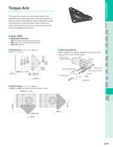
Introduction InductionMotors Watertight Motors ) 0.008 ✽ Screws must be purchased separately. Motor WasherSpring WasherNut GearheadMounting ScrewMounting Plate > 0.2 0.008 ) ) 0.2 0.2 0.008 ) 0.008 0.2 1.984 (50.4 MagneticBrake 2.362 (60 (84.85 3.341 4.69 (119.2) (100 3.937 0.413 ( 10.5) Shaft of Connected Device > Clutch &Brake ✽ M10 or 3/8-16 UNC Screw 0.335 ( 8.5) 4 Holes 0.16 (4) 0.38 1.874 > 0.008 Torque Arm (9.6) (47.6 > 0.2 ) > BrakePack 2.70 (68.5) > Right-Angle Gearheads
Open the catalog to page 5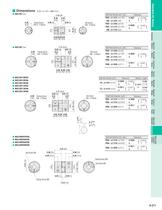
Scale 1/4, Unit = inch (mm) MCL20 Type > 1.14 (29) Shaft Hole Diameter ( d1, d2) > 0.39 0.39 F03 : 0.1875 ( 4.762) 0.00070 > Accessories Before Usinga StandardAC Motor MCL40F05F06 Shaft Hole Diameter ( d1, d2) MCL40F06F06 F05 : 0.3125 ( 7.937) 0.00090 >
Open the catalog to page 9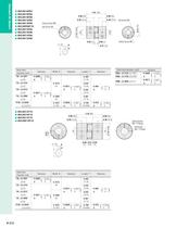
Shaft Hole Diameter ( Shaft Hole Diameter ( d2) d1) Tolerance Tolerance F05 : 0.3125 ( 7.937) 0.00090 > Shaft Hole Diameter ( d) Tolerance 10 : 0.3937 0.00090 >
Open the catalog to page 10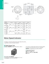
To mount in a panel, a flush mounting adapter EPUA-31 and round shapesocket EP11MS are provided with the speed indicator. >
Open the catalog to page 12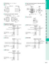
Watertight Motors Clutch &Brake Right-Angle Gearheads Before Usinga StandardAC Motor
Open the catalog to page 13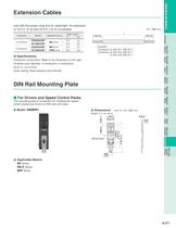
4.72 (145.5) 5.73 Before Usinga StandardAC Motor >
Open the catalog to page 15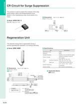
) 7.17 (182)UL style 3071 AWG 18 WhiteUL style 3122 AWG 22 White > : AWG 18x2 For regeneration current Connect to RG Terminal: AWG 22x2 For thermal signal (For > 302 F (150 а C) (NC) BHF Series, connect to I-COM and TP terminal) >
Open the catalog to page 16All ORIENTAL MOTOR catalogs and technical brochures
 Product Guide
36 Pages
 Product Guide
36 Pages
 Linear & Rotary Actuators
11 Pages
 Rack and Pinion System L Series
28 Pages
 DRS series
2 Pages
 DGII
DGII2 Pages
 EH series
12 Pages
 Servo Motors
7 Pages
 DSC Series
76 Pages
 Motors Torque
6 Pages
 BLH Series
36 Pages
 Electric CylindersEAC Series
2 Pages
 DSC Series
11 Pages
 Overview of Standard AC Motors
21 Pages
 BLE2 Series Brushless DC Motors
18 Pages
 BMU Series Brushless DC Motors
18 Pages
 Catalog Overview
24 Pages
 BXII Series
31 Pages
 RKII Series
51 Pages
 AZ Series
10 Pages
 CVK Series
24 Pages
 Stepper Motors
33 Pages
 Universal Controller, SCX11
4 Pages
 Standard AC Motors
9 Pages
 Servo motors
9 Pages
 Stepping Motors
23 Pages
 Cooling Module
8 Pages
 KII Series
16 Pages
 RK Series
4 Pages
 AS Series
4 Pages
 AR Series
4 Pages
 Controllers for Stepping Motors
18 Pages
 AC Motor Systems
62 Pages
 VEXTA Brushless DC Motors
60 Pages
 Clutch & Brake Motors
8 Pages
 Electromagnetic Brake Motors
44 Pages
 Reversible Motors
36 Pages
 Induction Motors
54 Pages


