Catalog excerpts
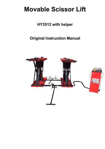
Movable Scissor Lift HY3512 with helper Original Instruction Manual
Open the catalog to page 1
Safety 1 Introduction Thoroughly read this manual before operating the lift and comply with the instructions. Always display the manual in a conspicuous location. Personal injury and property damage incurred due to non-compliance with these safety instructions are not covered by the product liability regulations. 2 Safety Instructions for Commissioning The lift may be installed and commissioned by authorized service personnel only. The standard lift version may not be installed and commissioned in the vicinity of explosives or flammable liquids, outdoors or in moist rooms (e.g. car wash). 3...
Open the catalog to page 3
CHAPTER 1 PACKING, TRANSPORT AND STORAGE ALL PACKING, LIFTING, HANDLING, TRANSPORT AND UNPACKING ORERATIONS ARE TO BE PERFORMED EXCLUSIVELY BY EXPERT PERSONNEL WITH KNOWLEDGE OF THE LIFT AND THE CONTENTS OF THIS MANUL 1.1 PACKING The lift is shipped disassembled into following parts The gross weight of the lift 1.2 TRANSPORT During loading and unloading operation, goods must be handled by vehicles or ships. At the arrival of the goods, verify that all items specified in the delivery notes are included. If finding missing parts, possible defects or damage due to transport, one should examine...
Open the catalog to page 5
CONSERVING THEMANUAL This manual is an integral part of the lift. The manual must be kept in the vicinity of the lift, so that the operator and maintenance staff must be able to locate and consult the manual quickly and at any time. Attentively reading Chapter 3, which contains important information and safety warning, is particularly Recommended. The lift is designed and manufactured according to European Standard The lifting, transport, unpacking, assembly, installation, starting up, initial adjustment and testing, extraordinary maintenance, repair, overhauls, transport and dismantling of...
Open the catalog to page 6
2.4 Basic structure The machine basement is made of cement and concrete. 2.5 Frame Make of steel connecting rod, main lifting platform, sliding board, pneumatic double tooth, and hydraulic oil tank. 2.6 Control box Under the control box is hydraulic oil tank and hydraulic pump, valve and other control system. On the control box is electrical system. Scissor lift is designed and built to lift all kinds of vehicles, all other use are unauthorized. In particular, the lift is not suitable for washing spray work. And not lift the vehicle whose weight exceeds the maximum weight. 2.7 Moving...
Open the catalog to page 7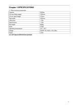
Chapter 3 SPECIFICATIONS 3.1 Main technical parameter Capacity Lift min stand height Total width Lifting time Descent time Noise Operating temperature 3.2 Lift layout dimension pict
Open the catalog to page 8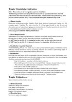
Chapter 4.Installation instruction Notes: These notes are for your guidance prior to installation The following operations must be performed exclusively by specialized technical staff with authorization from the manufacture or licensed dealer. If the operations are performed by other persons, serious personal injury and /or irreparable damage to the lift unit may result. 4.1 Select the site Always use architects plans when available. Check layout dimension requirements making sure that adequate space if available. The area where the lift will be located should be free of overhead...
Open the catalog to page 9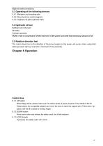
Machine earth connections 5.3 Operating of the following devices 5.3.1. Mechanic lock inserting pole. 5.3.2. Security device electromagnets 5.3.3. Hydraulic oil plant solenoid-valve 5.4 Hydraulic oil test Sufficient oil in the tank No leaks Cylinder operation NOTE: If oil is not present, fill the reservoir of the power unit with the necessary amount of oil 5.5 Rotation direction test The motor should turn in the direction of the arrow located on the power unit pump; check using brief start-ups (each start-up must last a maximum of two seconds). Control box 6.1.1 UP button When lifting...
Open the catalog to page 10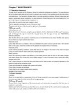
Chapter 7 MAINTENANCE 7.1 Operation frequency To keep the lift working at full efficiency, follow the indicated maintenance schedule. The manufacturer will not be responsible and will not honor the warranty as a result of non-compliance with the instructions indicated above. The frequency indicated refers to normal operating conditions; different frequencies will apply to particularly server conditions. ALL MAINTENANCE OPERATIONS MUST BE PERFORMED WITH THE LIFT STOPPING OR THE MAIN SWITCH PLACED AT “O”. When after the machine has been installed, check: That the opposite carriages arms are...
Open the catalog to page 11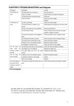
CHAPTER 8 TROUBLESHOOTING and Diagram TROUBLE: The main switch is not turned on Check Power on to restore if necessary The electrical wires are disconnected Check for correct voltage Replace Check the vehicle weight The motor direction of rotation is not Interchange the two phases on the main switch correct. The oil in the power unit is not sufficient. Check UP button and connection for proper operation. Replace if needed The maximum pressure valve clogged or Check and clean if dirty, or replace if faulty leaks The lowering valve does not close. Check and clean if dirty or replace if faulty...
Open the catalog to page 12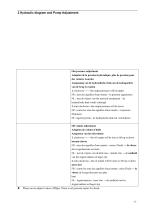
2 Hydraulic diagram and Pump Adjustment Out pressure adjustment Adaption de la pression hydraulique: plus de pression pour des voitures Lourdes Aanpassing van de hydraulische druk om de hefcapaciteit van de brug te regelen 1. clockwise--------the output pressure will be higher FR : sens des aiguilles d'une montre - la pression augmentera NL : met de wijzers van het uurwerk meedraaien – de hydraulische druk wordt verhoogd 2. anti-clockwise---the output pressure will be lower FR : contre les sens des aiguilles d'une montre - la pression diminuera NL: tegenwijzerzin : de hydraulische druk zal...
Open the catalog to page 13All Oreiko catalogs and technical brochures
-
Power Equipment
2 Pages
-
Movable Scissor Lift
15 Pages

