1990_OptoEMU
1 /8Pages

1990_OptoEMU
1 /8Pages
Catalog excerpts

OptoEMU Sensor DR (Demand Response) Features Description The OptoEMU Sensor™ Energy Monitoring Unit with Demand Response (DR) monitors the electrical energy used in your facility and then signals electrical equipment to turn on or off in response to a request from an electric utility, demand response aggregator, or curtailment service provider (CSP). To reduce peak energy use that triggers demand charges, electrical equipment loads can also be shed on predefined usage thresholds. The OptoEMU Sensor DR makes it easy to reduce your energy costs by managing energy consumption, taking advantage of demand response programs, and gaining control over your energy pricing. Why Monitor Energy? Traditionally, energy has been considered an overhead cost. Utility bills show few details about when and how electricity was used, and they arrive long after the energy was consumed. However, new energy pricing structures are changing traditional ways of looking at energy costs. Increasingly, commercial and industrial businesses are finding that they can significantly improve the bottom line by managing energy in the same way as other business costs such as people, assets, and inventory. The OptoEMU Sensor DR’s digital inputs gather data from up to two metering devices that emit pulses (such as a utility meter or submeter). The Sensor DR can also monitor up to 64 data inputs from Modbus devices (over serial and Ethernet). You can view this real-time and historical energy data through a secure online software service such as Pulse Energy or eSight. You choose the service that’s best for your business, and OptoEMU Sensor DR sends energy data directly to that service. Services usually provide graphs, energy usage comparisons, and other tools to analyze energy use in detail. Managing Demand Response Events The OptoEMU Sensor DR includes four signal relay outputs that can be used to automatically respond to a DR event by signaling equipment such as HVAC fans and chillers to turn on or off, or signal existing energy or building management systems to perform load shedding. Each Form C output can be wired for normally open or normally closed. Part Numbers Description Energy monitoring unit with Demand Response capability (Wired+Wireless) Energy monitoring unit with Demand Response capability (wired Ethernet) © 2012 Opto 22. All rights reserved. Dimensions and specifications are subject to change. Brand or product names used herein are trademarks or registered trademarks of their respective companies or organizations. DATA SHEET In addition, new Demand Response (DR) programs from energy providers offer opportunities to turn what used to be an overhead cost into a source of revenue. The OptoEMU Sensor DR lets you take advantage of these opportunities. Gathering and Viewing Energy Data OptoEMU Sensor DR (Demand Response) Monitor real-time energy usage from utility meters and equipment See and analyze energy data online Respond automatically or manually to Demand Response requests from electrical energy providers Exchange data with a SNAP PAC System, OPC or Modbus/TCP systems, and SQL databases Communicate over standard 10/100 Mbps Ethernet or wireless LAN (802.11a, b, or g) or both
Open the catalog to page 1
OptoEMU Sensor DR (Demand Response) OptoEMU Sensor DR (Demand Response) Configuration The Sensor includes an easy-to-use utility program for assigning an IP address for communication on your network, configuring inputs and an online data service, and entering the appropriate responses for a DR event. Communicating with Other Systems The OptoEMU Sensor DR can also communicate with other systems to coordinate energy management. Sensor data can be incorporated in a PAC Control strategy, a PAC Display HMI, and control systems that communicate through Modbus/TCP or OPC. DATA SHEET LAN (local area...
Open the catalog to page 2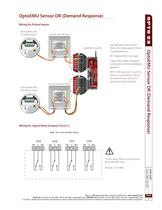
OptoEMU Sensor DR (Demand Response) Wiring for Pulsed Inputs Pulsing Meter with KY pulsing output Junction box with fuses Pin 7 (labeled NC) is not used. Contact your utility company if connections are not immediately apparent. NOTE: If this equipment is used in a manner not specified by Opto 22, the protection provided by the equipment may be impaired. Junction box with fuses Pulsing Meter with KYZ pulsing output Wiring for Signal Relay Outputs (Form C) Note: You must provide fusing. OptoEMU Sensor DR (Demand Response) Use with either two-wire KY (Form A) or three-wire KYZ (Form C) pulsing devices....
Open the catalog to page 3
OptoEMU Sensor DR (Demand Response) Wiring for Serial Ports RS-232 and RS-485 Pinouts Signal Direction OptoEMU Sensor DR (Demand Response) Signal Direction RS-485 2-Wire Serial device Middle of link Serial device End of link Serial device Middle of link RX – RX + COM TX/RX – TX/RX + Serial device End of link TX – TX + COM RX – RX + DATA SHEET Opto 22 • 43044 Business Park Drive • Temecula, CA 92590-3614 • www.opto22.com SALES 800-321-6786 • 951-695-3000 • FAX 951-695-3095 • [email protected] • SUPPORT 800-835-6786 • 951-695-3080 • FAX 951-695-3017 • [email protected] © 2012 Opto 22. All rights...
Open the catalog to page 4
OptoEMU Sensor DR (Demand Response) Specifications: OptoEMU Sensor DR Overall Unit Specifications OPTOEMU-SNR-DR1 Sturdy metal case Sturdy metal case Removable storage MicroSD card slot (for future use) MicroSD card slot (for future use) Backup battery Rechargeable (recharges whenever the unit has power), 3-year power-off data retention Rechargeable (recharges whenever the unit has power), 3-year power-off data retention Ethernet Communication (wired) Two independent 10/100 Mbps Ethernet network Two independent 10/100 Mbps Ethernet netinterfaces (RJ-45 connectors), each with a sepa- work interfaces...
Open the catalog to page 5
OptoEMU Sensor DR (Demand Response) Specifications (continued) Dry Contact Pulse Inputs OptoEMU Sensor DR supplies 15 volts to each external dry contact switch and senses switch closure. 15 VDC typical (supplied by OptoEMU Sensor DR) Short Circuit Current (Switch Closed) OptoEMU Sensor DR (Demand Response) Open Circuit Voltage (Switch Open) Maximum Allowable ON Resistance (Wire + Contact Resistance) Turn-on Time Turn-off Time Input-to-output Isolation Status indicators Signal Relay Outputs Contact Configuration SPDT relay (with NO and NC contacts) Line Voltage - Range Current Rating Surge Current...
Open the catalog to page 6All Opto 22 catalogs and technical brochures
 0491_PB
4 Pages
 1240_SNAP
6 Pages
 1556_SNAP
18 Pages
 1184_SNAP
5 Pages
 B3000-B
4 Pages
 0859_Solid
23 Pages
 1936_OptoEMU
11 Pages
 1120_SNAP
13 Pages
 1065_SNAP
42 Pages
 1684_SNAP
7 Pages
 1594_SNAP_
16 Pages
 1165
116514 Pages
 1662_OptoDataLink
4 Pages
Archived catalogs
 1487_OptoOPCServer
3 Pages
 1780_PAC
2 Pages
 1699_PAC
9 Pages
