1684_SNAP
1 /7Pages

1684_SNAP
1 /7Pages
Catalog excerpts

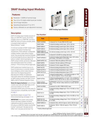
SNAP PAC Racks Features Description SNAP PAC I/O mounting racks are designed to hold an intelligent SNAP I/O processor—a SNAP PAC EB-series or SBseries brain or a SNAP PAC R-series on-the-rack controller— and several I/O modules. Both standard wired controllers and brains and Wired+Wireless models are mounted on these racks. Since SNAP analog, digital, and serial I/O modules all have the same footprint, customers using SNAP PAC racks can mix all these modules on the same I/O mounting rack. Field devices are wired directly to the top-mounted connectors on the modules plugged into each rack, or through breakout boards when additional wiring space is required. (See form 1756, the SNAP TEX Cables and Breakout Boards Data Sheet, for more information.) SNAP PAC racks can accommodate up to 4, 8, 12, or 16 I/O modules. Part numbers ending in -FM are Factory Mutual approved. SNAP PAC Racks module security, SNAP PAC racks have provisions for two 4-40 by ½-inch standard machine screws to hold each module in position. All SNAP PAC racks offer panel mounting and the option of DIN-rail mounting. DIN-rail adapter part numbers are shown in the table below. For more information, see form 1772, the SNAP TEX Mounting/Wiring Tools and Spare Parts Data Sheet. SNAP PAC racks require a 5 VDC power source. One power supply can usually power the rack, the I/O processor (controller or brain), and all modules on the rack. See form 1120, the SNAP Power Supplies Data Sheet, to choose a power supply. Part Numbers Part 8-module SNAP PAC rack 8-module SNAP PAC rack, Factory Mutual approved 12-module SNAP PAC rack 12-module SNAP PAC rack, Factory Mutual approved 16-module SNAP PAC rack, Factory Mutual approved SNAP rack DIN-rail adapter clip, 10pack Wide end cap for SNAP PAC racks DIN-rail assemblies, 10-pack Narrow end cap for SNAP PAC racks DIN-rail assemblies, 10-pack Opto 22 • 43044 Business Park Drive • Temecula, CA 92590-3614 • www.opto22.com SALES 800-321-6786 • 951-695-3000 • FAX 951-695-3095 • [email protected] • SUPPORT 800-835-6786 • 951-695-3080 • FAX 951-695-3017 • [email protected] © 2007–2012 Opto 22. All rights reserved. Dimensions and specifications are subject to change. Brand or product names used herein are trademarks or registered trademarks of their respective companies or organizations. DATA SHEET 4-module SNAP PAC rack, Factory Mutual approved SNAP PAC racks use a retention rail locking system that holds modules securely to the rack. Normally, a hold-down screw is not required. However, for applications that require additional SNAP-PAC-RCK8 (8-Module Position I/O Mounting Rack) Shown with SNAP-PAC-R1 controller and SNAP modules (all purchased separately) The module and rack design allows modules to simply “snap” on the mounting rack. Compatible with all SNAP PAC brains and R-series controllers, including Wired+Wireless™ models Secure mounting for SNAP I/O modules plus a SNAP brain or on-the-rack SNAP PAC controller Analog, digital, and serial modules on the same rack Panel or DIN-rail mounting Modules snap into place Factory Mutual-approved versions available
Open the catalog to page 1
SNAP PAC Racks Specifications 5.0 to 5.2 VDC @ 4.2 Amps max Replacement Fuse Rack Power Terminals Wire Size Operating Temperature Relative Humidity Agency Approvals Non -FM models: UL, CE, RoHS, DFARS -FM models: FM, CE, RoHS, DFARS 30 months from date of manufacture Module Mating Connector Pinout (female) 1 Power requirements shown are for a rack, a processor, and a full load of analog modules. Power requirements for SNAP serial and high-density modules are higher. See module data sheets. 2 “I/O Processor” means a SNAP PAC brain or SNAP PAC on-the-rack controller. For compatibility with legacy...
Open the catalog to page 2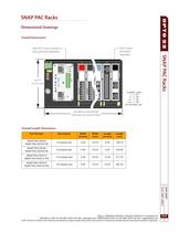
SNAP PAC Racks Dimensional Drawings Overall Dimensions SNAP module (purchased separately) SNAP PAC R-series controller or brain (purchased separately) See table for overall length dimensions for specific model Overall Length Dimensions Part Number Width (inches) Length (inches) DATA SHEET Opto 22 • 43044 Business Park Drive • Temecula, CA 92590-3614 • www.opto22.com SALES 800-321-6786 • 951-695-3000 • FAX 951-695-3095 • [email protected] • SUPPORT 800-835-6786 • 951-695-3080 • FAX 951-695-3017 • [email protected] © 2007–2012 Opto 22. All rights reserved. Dimensions and specifications are subject...
Open the catalog to page 3
Dimensional Drawings (continued) Right Side View with DIN-Rail Option Installed NOTE: CONSIDER NECESSARY SNAP-PAC RACK DIN RAIL CLIP MOUNTING OPTION TOLERANCE LEGEND CUSTOMER SUPPLIED NOTE: BE SURE TO CONSIDER (DIN RAIL MUST BE MOUNTED WITHOUT MODULE HOLD-DOWN SCREWS) SNAP RACK BASE EXTRUSION RACK BASE EXTRUSION END CAP For more information on DIN-rail mounting kits, see form 1772, the SNAP TEX Mounting/Wiring Tools and Spare Parts Data Sheet. Opto 22 • 43044 Business Park Drive • Temecula, CA 92590-3614 • www.opto22.com © 2007-2012 Opto 22. All rights reserved. Dimensions and specifications...
Open the catalog to page 4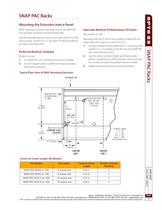
SNAP PAC Racks Mounting the Extrusion onto a Panel Alternate Method: Prefabrication of Panels NOTE: If you are not using hold-down screws, the SNAP PAC rack assembly should be mounted horizontally. Use the following steps to mount a rack onto a panel. For DINrail mounting, see form #1772, the SNAP TEX Mounting/Wiring and Spare Parts Data Sheet. (Product on site) 1. Use SNAP PAC rack mounting extrusion as template. 2. Use the diagram below to determine required product and option clearances. Typical Plain View of SNAP Mounting Extrusion Preferred Method: Template Mounting holes are in sets of...
Open the catalog to page 5
Assembling the Circuit Board, Rack Extrusion, and Din Clips, 1. (This step only for racks with three or more clips.) Slide one DIN clip to the middle position and secure with the rivet provided. For racks with four clips, add an additional middle clip. 2. Insert one edge of the circuit board into the extrusion. 3. Push down hard on the other edge to snap the board into place. 4. Attach one DIN clip to each end cap using the slots in the end caps as shown. DATA SHEET 5. Using the screws provided, secure an end cap and DIN clip assembly to each end of the extrusion. Removing the Circuit Board from...
Open the catalog to page 6All Opto 22 catalogs and technical brochures
 0491_PB
4 Pages
 1240_SNAP
6 Pages
 1556_SNAP
18 Pages
 1184_SNAP
5 Pages
 B3000-B
4 Pages
 1990_OptoEMU
8 Pages
 0859_Solid
23 Pages
 1936_OptoEMU
11 Pages
 1120_SNAP
13 Pages
 1065_SNAP
42 Pages
 1594_SNAP_
16 Pages
 1165
116514 Pages
 1662_OptoDataLink
4 Pages
Archived catalogs
 1487_OptoOPCServer
3 Pages
 1780_PAC
2 Pages
 1699_PAC
9 Pages

- Liebherr DC power supply
- Liebherr AC/DC power supply
- Liebherr management software
- Liebherr automation software
- Digital I/O
- Liebherr Windows software
- Liebherr control software
- Switching relay
- Analog I/O
- Digital IO module
- Liebherr monitoring software
- Liebherr industrial software
- Liebherr interface software
- Liebherr compact power supply
- Programmable logic controller
- Programming software
- Liebherr development software
- Network software