1120_SNAP
1 /13Pages

1120_SNAP
1 /13Pages
Catalog excerpts

SNAP Power Supplies Features SNAP Power Supplies Description SNAP power supplies provide the best source of AC or DC power for your Opto 22 SNAP PAC hardware. Packaged in a compact and sturdy housing, SNAP power supplies include a built-in fuse, an LED status indicator, and an ON/OFF power switch for ease of use. The SNAP-PS24 and SNAP-PS24U power supplies are designed for either of two purposes: • to provide primary power for a SNAP PAC S-series controller • to provide 24 volts of DC loop power for SNAP analog modules mounted on a SNAP PAC rack The SNAP-PS5, SNAP-PS5-24DC, and SNAP-PS5U power supplies are designed to provide 5 VDC power for a SNAP PAC rack with an I/O processor (SNAP PAC brain or R-series controller) and I/O modules mounted on the rack. The combination of a rack, processor, and modules is called an I/O unit. Opto 22 recommends using one SNAP power supply for each I/O unit and for each controller. Choose the power supply based on the load required for the I/O unit. See the power requirements tables starting on page 11 for help in determining the power supplies you need. Additional information on using power supplies can be found in the Opto 22 technical note Using Power Supplies with Opto 22 Systems (form #1271, available on our website, www.opto22.com). All SNAP power supplies except the SNAP-PS5-24DC require AC input power. The SNAP-PS5U and SNAP-PS24U accommodate a wide range of AC input voltages, from 100 to 250 VAC. AC or DC input power connections, as required by the model, are made to a removable terminal strip on top of the power supply. DC output power is then ready to be hooked up to the controller or rack using the attached wiring harness. SNAP power supplies work with Wired+Wireless™ PACs and I/O units as well as standard wired PACs and I/O. Notes for legacy hardware: SNAP power supplies are also compatible with Ethernet-based SNAP Ultimate, SNAP Ethernet, and SNAP Simple I/O, and with serial-based SNAP I/O units such as those with a B3000, SNAP-HA, or SNAP-B3000-MODBUS brain. Part Numbers Part Description SNAP Power Supply 120 VAC input; 5 VDC, 4 A output SNAP Power Supply 24 VDC input; 5 VDC, 4 A output SNAP Power Supply 100–250 VAC input; 5 VDC, 5 A output SNAP Power Supply 120 VAC input; 24 VDC, 3/4 A output SNAP Power Supply, 100–250 VAC input; 24 VDC, 1-1/4 A output Opto 22 • 43044 Business Park Drive • Temecula, CA 92590-3614 • www.opto22.com SALES 800-321-6786 • 951-695-3000 • FAX 951-695-3095 • [email protected] • SUPPORT 800-835-6786 • 951-695-3080 • FAX 951-695-3017 • [email protected] © 2006–2012 Opto 22. All rights reserved. Dimensions and specifications are subject to change. Brand or product names used herein are trademarks or registered trademarks of their respective companies or organizations. DATA SHEET The SNAP-PS5-24DC DC-to-DC power supply requires a 24 VDC input and is ideal for systems using DC backup power. Each SNAP power supply can be mounted in one of two ways: next to the controller or SNAP I/O unit it powers, using the standard panel-mounting base, or directly on a DIN rail using the optional DIN-rail adapter. SNAP Power Supplies Built-in fuse, ON/OFF power switch, and LED indicator Convenient panel mounting; optional DIN-rail mounting Easy connections Wide input voltage range Factory Mutual approved (except SNAP-PS5U and SNAP-PS24U)
Open the catalog to page 1
SNAP Power Supplies Specifications SNAP-PS5 Input Voltage Output Voltage Output Current SNAP Power Supplies Maximum Input Current Draw See the drawings starting on page 7. See the drawings starting on page 7. Operating Temperature Storage Temperature Torque, connector screws Opto 22 PN: SNAP-FUSE1AB Vendor PN: GDC-1A (Bussman) Opto 22 PN: SNAP-FUSE2AB Vendor PN: GDB-2A (Bussman) Internal fuse Agency Approvals Input Voltage Output Voltage Output Current Maximum Input Current Draw See drawings starting on page 7. Operating Temperature Storage Temperature Torque, connector screws Opto 22 PN: SNAP-FUSE1AB...
Open the catalog to page 2
SNAP Power Supplies Always use a separate field supply Power wiring guidelines Use a separate power supply for the field side of the I/O. Using the rack supply for field actuation and monitoring defeats the isolation the I/O module offers and therefore increases the chance of a ground loop within the control system. Additionally, a sudden change of current on the field side can cause undesirable voltage fluctuations that may interfere with the controller or I/O unit’s operation. Installation Panel Mounting (standard) Mount the SNAP power supply in a location where the attached red and black power...
Open the catalog to page 3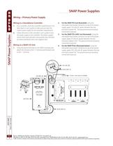
SNAP Power Supplies Wiring—Primary Power Supply Wiring to a Standalone Controller 1. Wiring to a SNAP I/O Unit 1. Using the power terminals on the SNAP mounting rack, attach the red wire to the “+” terminal and the black wire to the “-” terminal. For the SNAP-PS5 (not illustrated): Using the removable input power connector on top of the power supply, apply 120 volts AC power between the two terminals marked “AC.” The ground terminal should be connected to ground. For the SNAP-PS5-24DC (not illustrated): Using the removable input power connector on top of the power supply, apply 24 volts DC power...
Open the catalog to page 4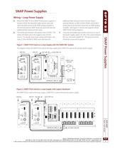
SNAP Power Supplies Wiring—Loop Power Supply 5. additional field wiring terminal strip (see Figure 1 example below), or refer to forms #1065 and #1066 if wiring directly to the field connectors on SNAP analog modules (see Figure 2). See the next page for similar SNAP-PS24U wiring diagrams. Using the removable input power connector on top of the power supply, apply 120 volts of AC power between the two terminals marked “AC.” The ground terminal should be connected to ground. Figure 1. SNAP-PS24 Used as a Loop Supply with the SNAP PAC System This diagram shows the SNAP-PS24 used as the loop supply...
Open the catalog to page 5
SNAP Power Supplies Wiring—Loop Supply (continued) Figure 1. SNAP-PS24U Used as a Loop Supply with the SNAP PAC System SNAP Power Supplies This diagram shows the SNAP-PS24U used as the loop supply and a SNAP-PS5U used as the primary power supply. Figure 2. SNAP-PS24U Used as a Loop Supply with Legacy Hardware DATA SHEET The SNAP-PS24U is used as the loop supply; a SNAP-PS5U is used as the primary power supply. Opto 22 • 43044 Business Park Drive • Temecula, CA 92590-3614 • www.opto22.com SALES 800-321-6786 • 951-695-3000 • FAX 951-695-3095 • [email protected] • SUPPORT 800-835-6786 • 951-695-3080...
Open the catalog to page 6All Opto 22 catalogs and technical brochures
 0491_PB
4 Pages
 1240_SNAP
6 Pages
 1556_SNAP
18 Pages
 1184_SNAP
5 Pages
 B3000-B
4 Pages
 1990_OptoEMU
8 Pages
 0859_Solid
23 Pages
 1936_OptoEMU
11 Pages
 1065_SNAP
42 Pages
 1684_SNAP
7 Pages
 1594_SNAP_
16 Pages
 1165
116514 Pages
 1662_OptoDataLink
4 Pages
Archived catalogs
 1487_OptoOPCServer
3 Pages
 1780_PAC
2 Pages
 1699_PAC
9 Pages
