1065_SNAP
1 /42Pages
1065_SNAP
1 /42Pages
Catalog excerpts

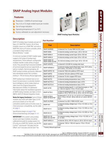
SNAP Analog Input Modules Features Resolution = 0.004% of nominal range Two, 4, 8, or 32 single-ended inputs per module Out-of-range indication Operating temperature 0 °C to 70 °C Factory calibrated; no user adjustment necessary Description SNAP I/O analog input modules are part of Opto 22’s SNAP PAC System. All of these modules mount on a SNAP PAC rack with a SNAP PAC brain or R-series controller, either a standard wired model or a Wired+Wireless™ model. A minimum number of SNAP module types support a full range of analog input requirements. These software-configurable modules handle a wide variety of signal levels. They provide high resolution (0.004% of nominal range) for precise signal levels, as well as multiple-channel packaging. All SNAP analog modules are factory calibrated and individually tested. Part numbers ending in -FM are Factory Mutual approved. SNAP analog input modules have an onboard microprocessor to provide modulelevel intelligence, which makes them an ideal choice for Original Equipment Manufacturers (OEMs). For additional information about the standalone operation of SNAP analog modules, see Opto 22 form #0876, SNAP I/O Module Integration Guide. Notes for legacy hardware: Some of these modules also work with older Opto 22 I/O processors (brains or on-the-rack controllers) and M-series or B-series racks. To check processor compatibility, see the table on page 3. Specifications begin on page 4. For dimensional drawings, see pages 31–41. 2-channel analog current input, -20 to +20 mA 4-channel analog current input -20 to +20 mA 8-channel analog current input -20 to +20 mA 2-channel 0–25,000 Hz analog rate input 4-channel analog resistor/thermistor input, 40 K ohms, 20 K ohms, 10 K ohms, or 5 K ohms 2-channel analog temperature input, ICTD 4-channel analog temperature input, ICTD 8-channel analog temperature input, ICTD 2-channel analog type E, J, or K thermocouple or -150 to +150 mV input or -75 to +75 mV input 2-channel analog type B, C, D, G, N, T, R, or S thermocouple or -50 to +50 mV DC or -25 to +25 mV DC input 2-channel analog voltage input -10 to +10 VDC or -5 to +5 VDC 4-channel analog voltage input -10 to +10 VDC or -5 to +5 VDC 8-channel analog voltage input -10 to +10 VDC or -5 to +5 VDC 32-channel analog voltage input -10 to +10 VDC or -5 to +5 VDC DATA SHEET SNAP-AIMA-32 32-channel analog current input -20 to +20 mA SNAP-AIMA-32-FM* IMPORTANT: Any system using analog sensors and input modules should be calibrated annually for analog signals. For I/O units on a SNAP PAC System, use the PAC Control™ commands “Calculate and Set Offset” and “Calculate and Set Gain.” For Part Number SNAP Analog Input Modules SNAP Analog Input Modules * Factory Mutual approved Opto 22 • 43044 Business Park Drive • Temecula, CA 92590-3614 • www.opto22.com SALES 800-321-6786 • 951-695-3000 • FAX 951-695-3095 • [email protected] • SUPPORT 800-835-6786 • 951-695-3080 • FAX 951-695-3017 • [email protected] © 2001–2012 Opto 22. All rights reserved. Dimensions and specifications are subject to change. Brand or product names used herein are trademarks or registered trademarks of their respective companies or organizations.
Open the catalog to page 1
SNAP Analog Input Modules other Ethernet-based I/O units, you can also use PAC Manager™ software to calculate and set offset and gain. All SNAP analog input modules are transformer isolated and optically isolated from all other modules and from the SNAP I/ O processor. The modules in this data sheet do not have channel-to-channel isolation, however. (If you need isolated analog modules, see Opto 22 form #1182.) Optical isolation provides 4,000 volts of transient (4,000 V for 1 ms) protection for sensitive control electronics from industrial field signals. Transformer isolation prevents ground...
Open the catalog to page 2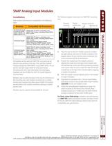
SNAP Analog Input Modules Installation Note module and processor compatibility in the following table: Modules The following diagram shows part of a SNAP PAC mounting rack. Processor connector Module position zero Module connectors Retention bar SNAP PAC R-series controllers and SNAP PAC brains, including Wired+Wireless models Also the following legacy brains: SNAP Ethernet, SNAP Simple, SNAP Ultimate; SNAP-DNP-ASDS; SNAP OEM SNAP PAC R-series controllers and SNAP PAC brains, including Wired+Wire2-channel inputs less models (except SNAPAlso the following legacy brains: AIRTD-10 and SNAP Ethernet,...
Open the catalog to page 3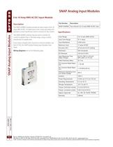
SNAP Analog Input Modules 0 to 10 Amp RMS AC/DC Input Module Part Number The SNAP-AIARMS module provides an input range of 0 to 10 amps RMS AC/DC. An ideal input is the 5-amp secondary of a standard current transformer used to monitor AC line current. SNAP Analog Input Modules SNAP-AIARMS Two-channel 0 to 10 amp RMS AC/DC input The SNAP-AIARMS module may be used to monitor AC current to greater than a 100-amp range, using a current transformer of suitable ratio. Specifications Input Range Input Over-Range If you need a module with channel-to-channel isolation, see form #1182, the SNAP Isolated...
Open the catalog to page 4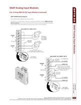
SNAP Analog Input Modules 0 to 10 Amp RMS AC/DC Input Module (continued) SNAP-AIARMS Wiring Diagrams Two possible wiring diagrams are shown below. Terminals 3,4, 7, and 8 share a common connection inside the module. Make sure you observe polarity when connecting the second channel. To avoid a potentially hazardous short, double-check wiring before turning on the current to be monitored. SNAP-AIARMS TWO CURRENT INPUTS LINE CURRENT TO MINIMIZE CHANNEL CROSS TALK, DO NOT SHARE TERMINAL BETWEEN CHANNELS SNAP MODULE FIELD CONNECTOR SNAP-AIARMS TWO CURRENT INPUTS DASHED LINES 0 TO 10 AMP AC/DC COMMON...
Open the catalog to page 5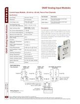
SNAP Analog Input Modules Current Input Module, -20 mA to +20 mA, Two or Four Channels Specifications Part Number Two-channel analog current input, -20 mA to +20 mA Over-Range Limits Four-channel analog current input, -20 mA to +20 mA Input Response Time (% of span/ delta I/delta tme) DC Common Mode Rejection AC Common Mode Rejection Maximum Survivable Input The SNAP-AIMA and SNAP-AIMA-4 modules provide an input range of -20mA to +20mA. The SNAP-AIMA has two channels, and the SNAP-AIMA-4 has four. If you need a similar module with more channels, see page 9. Check the table on page 3 for I/O processor...
Open the catalog to page 6All Opto 22 catalogs and technical brochures
 0491_PB
4 Pages
 1240_SNAP
6 Pages
 1556_SNAP
18 Pages
 1184_SNAP
5 Pages
 B3000-B
4 Pages
 1990_OptoEMU
8 Pages
 0859_Solid
23 Pages
 1936_OptoEMU
11 Pages
 1120_SNAP
13 Pages
 1684_SNAP
7 Pages
 1594_SNAP_
16 Pages
 1165
116514 Pages
 1662_OptoDataLink
4 Pages
Archived catalogs
 1487_OptoOPCServer
3 Pages
 1780_PAC
2 Pages
 1699_PAC
9 Pages

- Power supply unit
- DC power supply
- AC/DC power supply
- Automation software solution
- Management software solution
- Digital I/O
- Windows software
- Control software
- Switching relay
- Analog I/O
- Digital IO module
- Monitoring software solution
- Industrial software
- Interface software
- Compact power supply
- Programmable logic controller
- Programming software
- Development software
- Network software