
- Catalogs
- OPTEX Measurement Division
- Air-Slide

Air-Slide

Air-Slide
Active Infrared Sensor Air-Slide: Overview
This document provides detailed technical specifications and mounting guidelines for the Air-Slide Active Infrared Sensor, focusing on its detection area, mounting heights, and adjustable detection patterns.
1. Detection Area and Sensor Rows
The sensor's detection area is divided into multiple rows (1st to 5th), each corresponding to specific vertical zones. The emitting area is segmented into rows labeled from 2nd to 5th, with the 1st row separately identified. These rows define the vertical coverage of the sensor.
2. Mounting Heights and Corresponding Detection Distances
| Mounting Height (mm/inches) | Detection Distances (mm/inches) by Row |
|---|---|
| 2200 (7’3”) | A: 220 (9”), B: 460 (1’6”), C: 860 (2’10”), D: 1330 (4’4”), E: 2450 (8’), F: 1760 (5’9”), G: 1110 (3’8”) |
| 2000 (6’7”) | A: 200 (8”), B: 420 (1’5”), C: 780 (2’7”), D: 1210 (3’12”), E: 2230 (7’4”), F: 1600 (5’3”), G: 1010 (3’4”) |
| 2700 (8’10”) | A: 270 (11”), B: 560 (1’10”), C: 1050 (3’5”), D: 1630 (5’4”), E: 3000 (9’10”), F: 2160 (7’1”), G: 1360 (4’6”) |
| 3000 (9’10”) | A: 300 (12”), B: 630 (2’), C: 1180 (3’10”), D: 1820 (5’12”), E: 3350 (10’12”), F: 2400 (7’11”), G: 1520 (4’12”) |
| 2500 (8’2”) | A: 250 (10”), B: 520 (1’9”), C: 970 (3’2”), D: 1510 (4’11”), E: 2780 (9’1”), F: 2000 (6’7”), G: 1260 (4’2”) |
The table shows the relationship between mounting height and the horizontal detection distances for points labeled A through G, indicating the sensor’s coverage footprint at various installation heights.
3. Detection Pattern Adjustments
The sensor’s detection pattern can be adjusted horizontally by tilting 7° to the left or right, or vertically by changing the depth from shallow to deep. These adjustments modify the detection area to optimize coverage and eliminate unwanted detection zones (marked as eliminatable areas).
Front View: Shows standard pattern and patterns when tilted 7° left or right, highlighting eliminatable areas to avoid false detections.
Side View: Illustrates pattern changes from shallow to deep detection zones, also indicating eliminatable areas for fine-tuning sensor coverage.
4. Specifications and Dimensions
The document includes outer dimensions of the Air-Slide sensor in millimeters and inches, ensuring compatibility with installation requirements. Specific numerical values are not detailed here but are essential for precise mounting and integration.
Critical Information and Best Practices
- Mount the sensor at recommended heights to achieve optimal detection distances.
- Adjust the detection pattern angle (left/right tilt) and depth (shallow/deep) to tailor the sensor coverage and eliminate unnecessary detection zones.
- Refer to the provided tables and diagrams to understand the spatial coverage and avoid blind spots or false alarms.
- Ensure proper alignment according to the front and side view patterns for effective sensor performance.
Catalog excerpts
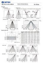
Active Infrared Sensor DETECTION AREA unit[mm] Mounting height Mounting height SIDE VIEW : Eliminatable area Pattern when changed to the shallowest : Eliminatable area : Eliminatable area Pattern when standard : Eliminatable area Pattern when changed to the deepest Pattern when changed 7° to Right : Eliminatable area : Eliminatable area Pattern when standard Pattern when changed 7° to Left FRONT VIEW
Open the catalog to page 1
Active Infrared Sensor Cover color Mounting height Detection area Detection method Depth angle adjustment Width angle adjustment Power supply Power consumption Operation indicator(left) Active Infrared Reflection Green / Stand-by Blinking Orange / Orange / 3rd to 5th rows detection Operation indicator(right) Output hold time Response time Operating temperature None / Stand-by Yellow /1st row adjustment mode 1 Power & Primary activation output 1 Presence / Secondary activation 1 Area adjustment tool
Open the catalog to page 2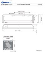
OUTER DIMENSIONS Active Infrared Sensor Touchless plate Touch Free Wave hand here
Open the catalog to page 3All OPTEX Measurement Division catalogs and technical brochures
 AIR-WAVE
3 Pages
 OP-12C
2 Pages
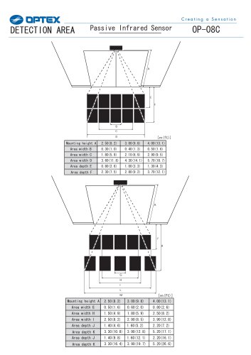 OP-08C
3 Pages
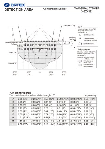 Combination Sensor
4 Pages
 HX-80
HX-802 Pages
 RXC-ST
2 Pages
 fmx series
2 Pages
 RXC-DT
2 Pages
 BX-80N
2 Pages
 AX-70
AX-702 Pages
 TSC-10(E)
2 Pages
 LX-402
2 Pages
 HX-40
HX-402 Pages
 VX infinity series
2 Pages
 BX-100PLUS
2 Pages
 smart line series
8 Pages
 CS, CS-HT series
2 Pages
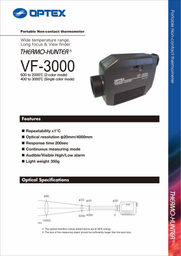 VF-3000
2 Pages
 Built-in 2 BF type
2 Pages
 PT-3LF
2 Pages
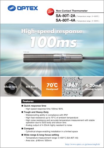 SA-80
SA-802 Pages
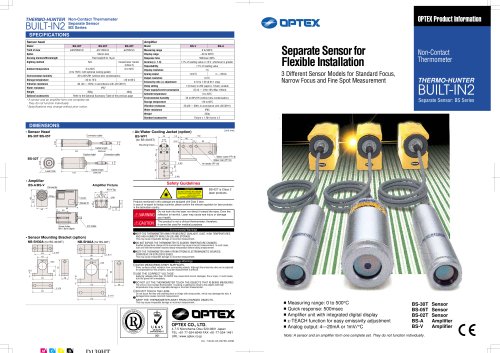 Built-in 2 BS Series
2 Pages
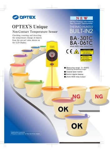 Built-in 2 BA-TC Series
2 Pages
 Built-in 2 BA Series
2 Pages
 PT-02LD
2 Pages
 PT-2LD
2 Pages
 PT-7LD
2 Pages

- Digital I/O
- IO module
- Digital pyrometer
- Analog I/O
- Digital IO module
- Industrial thermometer
- °C thermometer
- Fieldbus I/O module
- IR pyrometer
- Analog IO module
- Displacement transducer
- Waterproof thermometer
- Portable pyrometer
- Linear displacement sensor
- DIN rail mounted I O module
- Non-contact thermometer
- Stationary pyrometer
- Non-contact displacement sensor
- Industrial displacement sensor
- Thermometer with LCD display