- Catalogs
- Onto Innovation Inc.
- Edge Defectivity for Immersion Lithography
Edge Defectivity for Immersion Lithography
1 /1Page

Edge Defectivity for Immersion Lithography
1 /1Page
Catalog excerpts
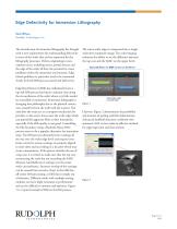
Edge Defectivity for Immersion Lithography Matt Wilson Rudolph Technologies, Inc. The introduction of immersion lithography has brought with it new requirements for understanding defectivity in areas of the wafer that are less important for dry lithography processes. Defects originating in nonexposure areas, including streets, partial devices and the edge of the wafer all have the potential to create problems within the immersion environment. Edge related problems in particular need to be monitored closely for both EBR process control and defectivity. Edge Bead Removal (EBR) has traditionally been a top side EBR process leaving an exclusion zone along the circumference of the wafer where very little would be controlled or monitored. Immersion lithography is changing that philosophy due to the physical contact now created between the wafer and the scanner. Not only does the water act as a transport mechanism for particles, it also exerts forces onto the wafer edge which can potentially aggravate films at their boundaries, especially if the EBR quality is not good. Controlling the film boundary using a Backside Rinse (BSR) process seems to be a popular alternative for immersion steps. The BSR process ultimately leaves coatings all the way over the wafer edge bevel and requires even better control to ensure coatings are properly aligned to each other and not ending in a location which may create contaminants. If the process includes the use of a top coat, it is critical to make sure that the top coat is protecting the resist but not exceeding the BARC (Bottom Anti-Reflective Coating) over the entire wafer circumference. Incorrect overlap of the coatings can be caused from excessive ‘chop’ in the EBR line, off-center EBR processing, or EBR that is simply out of tolerance. Different tracks with multiple coating modules can have slight variations in performance and can be difficult to monitor and optimize. Figure 1 is a typical example of EBR on the BSR process. The entire wafer edge is compressed into a single, wafer-level composite image. The color imaging enhances the ability to see the difference between the top coat and the BARC on the upper bevel. Likewise, Figure 2 demonstrates the possibility and location of peeling and film delamination. Advanced darkfield detection combined with automatic SEM review make an effective method for edge inspection and data analysis.
Open the catalog to page 1All Onto Innovation Inc. catalogs and technical brochures
 Onto Innovation
19 Pages
 Solid State Technology
6 Pages
 Use style: paper title
6 Pages
 rudolph technologies
1 Page


- Management software solution
- Analysis software solution
- Process software
- Windows software
- Real-time software
- Computer-aided design software
- Design software solution
- Monitoring software solution
- Industrial software
- Inspection system
- Visualization software solution
- Automatic tester
- Automated software
- Industrial tester
- Thickness gauge
- Development software
- Reporting software
- Machine software
- Optimization software
- Automatic inspection system