
Catalog excerpts
This logger can be used with sensors that may be installed in an energized electrical enclosure or on an energized conductor. Installation of sensors in an energized electrical enclosure or on an energized conductor can result in severe injury or death. These sensors are for installation by qualified personnel only. To avoid electrical shock, do not install or service these sensors unless you are qualified to do so. Disconnect and lock out all power sources during installation and servicing. Please read the users manual for instructions and use. Contact Information For support, please...
Open the catalog to page 2
This section discusses the following topics: Overview Specifications Key Features FlexSmart Modules Smart Sensors Components Accessories > The HOBO Energy Logger Pro is a modular, reconfigurable data logging system used in energy and industrial monitoring applications. The 15-channel system enables you to quickly and easily perform a broad range of monitoring applications. You can use the HOBO Energy Logger Pro with FlexSmart modules, which convert signals from many types of Onset and third-party sensors. You can also use any Smart Sensor that is compatible with the HOBO Weather station or...
Open the catalog to page 5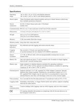
Operatingrange-20 to 50аC (-4 to 122аF) with alkaline batteries -40 to 60аC (-40 to 140аF) with lithium batteries Sensor inputs Three FlexSmart multi-channel modules and up to 6 Smart Sensors (which may have multiple parameters/channels) Sensor connectorsSix RJ-12 Smart Sensor jacks plus 3 FlexSmart module slots Communication RS-232 via 3.5 mm serial port or/and 9-pin D-Sub connector Dimensions 15.6 cm x 8.4 cm x 4.6 cm (6.13" x 3.31" x 1.81") Weight 435 g (15.23 oz) with batteries 238 g (8.33 oz) without batteries Memory 512K nonvolatile flash data storage Memory modes Stop when full; wrap...
Open the catalog to page 6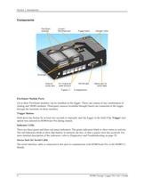
Figure 1: Components FlexSmart Module Ports Up to three FlexSmart modules can be installed on the logger. These can consist of any combination of Analog and TRMS modules. Third-party sensors (available through Onset) are connected to the logger through the terminals on these modules. Trigger Button Hold down the button for at least two seconds to manually start the logger in the field if the Trigger startoption was selected in HOBOware Pro during launch. Indicator LEDs There are three green and three red status indicators. The green indicators blink to show status or activity. The red...
Open the catalog to page 8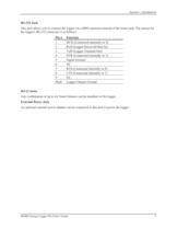
Section 1: Introduction RS-232 Jack This port allows you to connect the logger via a DB9 connector instead of the stereo jack. The pinout for the logger's RS-232 connector is as follows: Pin # Function 1 DCD (Connected internally to 4) 2 RxD (Logger Received Data In) 3 TxD (Logger Transmit Out) 4 DTR (Connected internally to 1) 5 Signal Ground 6 NC 7 RTS (Connected internally to 8) 8 CTS (Connected internally to 7) 9 NC Shell Logger Chassis Ground RJ-12 Jacks Any combination of up to six Smart Sensors can be installed on the logger. External Power Jack An optional external power adapter can...
Open the catalog to page 9
Section 2: Setup and Test Before deploying the logger, read this section thoroughly and follow all of the procedures at least once. This will ensure that you are comfortable enough with the logger and with HOBOware Pro software to get the most out of your deployment. It will also verify that the logger is configured properly. Note: Refer to the HOBOware Users Guide for detailed information about setup. > You will need the following items to prepare the logger for use: Eight 1.5V Alkaline Batteries and small Phillips head screwdriver (for battery door); or external power source At least one...
Open the catalog to page 11
Section 2: Setup and Test To set up the logger, take the following steps: 1.Insert the batteries or connect external power source.To install batteries, use a Phillips head screwdriver to loosen the screw on the back of the battery compartment door. Remove the door. Install eight fresh 1.5 V batteries, being careful to match the polarity marked in the battery compartment. (Refer to Selecting Batteries on page 17 for tips on selecting the right battery type for your application.) Replace the battery compartment door and tighten the screw to secure it. Do not over-tighten the screw. See...
Open the catalog to page 12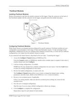
Section 2: Setup and Test Installing FlexSmart Modules Remove the protective cap from the module connector on the logger. Align the connector on the back of the FlexSmart module with the connector on the logger, and gently press the module into place. Figure 1: FlexSmart Module Configuring FlexSmart Modules While Smart Sensors are designed and preconfigured for specific purposes, FlexSmart modules are user-configurable to accommodate a wide range of Onset and third-party sensors. To take advantage of this adaptability, HOBOware Pro lets you configure these modules at launch time, or create...
Open the catalog to page 13
Section 2: Setup and Test Once all Smart Sensors have been connected and FlexSmart modules have been configured, access the Launch window in HOBOware Pro and take the following steps: 1.Select the correct battery type (alkaline or lithium). If the battery type is not set correctly, the batteries will not report their power accurately. 2.Review the list of channels. Make sure all of your sensors and modules are listed in the Launch window in HOBOware Pro. The FlexSmart modules and Smart Sensors are listed in ascending order by serial number. If more than 15 data channels are connected, the...
Open the catalog to page 14
Section 2: Setup and Test You can verify logger status by looking at the indicator lights on the logger. The LEDs blink to let you know if the logger is waiting for a delayed or button start, or if the logger is already logging. Other LEDs blink to warn you when battery power or memory is running low, or if there is a sensor error. Refer to Indicator LED Behavior on page 29 for details. You can get more detailed information about battery power, sensor readings, and memory in HOBOware Pro at any time, whether the logger is logging or not. Refer to the HOBOware Users Guide for details about...
Open the catalog to page 15
Section 2: Setup and Test It is a good idea to quickly test the logger before each deployment, especially if the logger has been stored unused for a long period. To test the logger, take the following steps: 1.Set up the logger (attach sensors, etc.) and start HOBOware Pro. 2.Access the Launch window and verify that HOBOware Pro detects all of the connected modules and sensors. 3.Enter a logging interval of a few seconds so that your test will yield enough data to look at, and select the loggers internal battery channel. Make sure the logger is configured to start logging immediately upon...
Open the catalog to page 16All ONSET catalogs and technical brochures
-
HOBO® MX1105 Data Logger
3 Pages
-
HOBO® MX100 Data Logger
3 Pages
-
HOBO UX90-004x
6 Pages
-
HOBO UX90-005x/-006x
7 Pages
-
HOBO UX100-002x
6 Pages
-
HOBO UX100-003
8 Pages
-
HOBO UX100-014M
8 Pages
-
InTemp® CX403
3 Pages
-
HOBO® MX2204 Data Logger
3 Pages
-
InTemp® CX702 Data Logger
2 Pages
-
InTemp® CX602 Data Logger
2 Pages
-
InTemp® CX5000
2 Pages
-
T-WNB-3D-240 Sensor
2 Pages
-
S-FS-TRMSA Sensor
2 Pages
-
S-RGF-M002 Sensor
2 Pages
-
HOBO® Energy Logger
2 Pages
-
S-THB-M008 Sensor
3 Pages
-
T-VER-PX3UL Sensor
2 Pages
-
S-WCF-M003 Sensor
3 Pages
-
HOBO® MX2301A Data Logger
3 Pages
-
HOBO® RX3000 Data Logger
3 Pages
-
RXW-THC-xxx Sensor
3 Pages
-
MX1102
2 Pages
-
ZW series
2 Pages
-
HOBO MX2300
2 Pages
-
UX90
2 Pages
-
HOBO USB Micro Station
2 Pages
-
Catalog 2014
46 Pages
-
pressure data-logger
8 Pages


