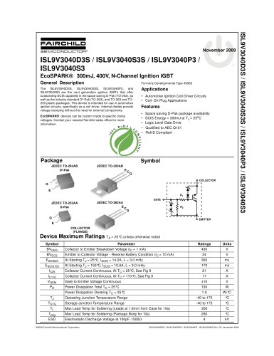
LED Power Supply WebDesigner Product Overview
1 /2Pages
LED Power Supply WebDesigner Product Overview
1 /2Pages
Catalog excerpts

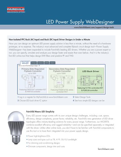
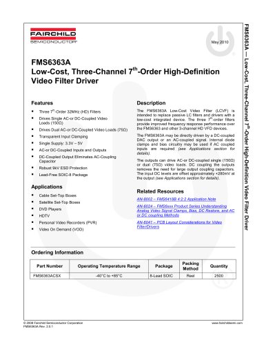
Non-Isolated PFC Buck (AC Input) and Buck (DC Input) Driver Designs in Under a Minute Now you can design an optimum LED power supply solution in less than a minute, without the need of a hardware prototype, at no expense. The industry's most advanced and complete flyback circuit design tool—Power Supply WebDesigner—has been expanded to include Fairchild's leading LED drivers. Whether you are a power expert or not, you can specify, simulate and analyze your design faster and easier than ever before. And it is the industry's first LED online tool that helps design EMI filters and predicts PF and THD. Power Supply Design I Analysis I BOM I Report Click on one of the following to begin: © Primary-Side Regulated Flyback Converter Secondary-Side Regulated Flyback Converter Featuring FSGM & FSL series 1 Log in or register for MyFairchild at www.fairchildsemi.com 3 Choose LED buck driver IC option 2 Select Design Tools rFairchild Means LED Simplicity V Every LED power range comes with its own unique design challenges, including: cost, space, efficiency, design complexity, power factor, reliability, etc. Fairchild's new generation of LED driver topologies offers industry-leading solutions for every power range. Furthermore, our MOSFETs combine excellent efficiency and rugged reliability—and can be specified separately or integrated with the driver. Unlike other online tools, you don't have to be familiar with Fairchild components to use this tool or to have them integrated into your power supply design. • Power high-brightness LEDs • Lamp sizes and types such as T8, Al 9, GU1 0/candlelight • For dimming and non-dimming designs • Eliminate components, design time and costs
Open the catalog to page 1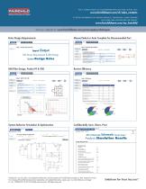
FOR A COMPLETE LISTING OF SALES REPRESENTATIVES AND SALES OFFICES, VISIT: TO RECEIVE INFORMATION ON FAIRCHILD PRODUCTS, TRADESHOWS, ONLINE SEMINARS AND OTHER ITEMS, REGISTER HERE FOR UPDATES: Enter Design Requirements Manual Select or Auto Complete for Recommended Part I Step 1: Design Requirements Input Output LED Driver Requirements & LED Ratings System Design Rules EMI Filter Design, Predict PF & THD Requirements ^^^^^^^B System Behavior Simulation & Optimization AC Input Voltage Configuration AC Input Transient Sce?< Step 2: Operating Condition MOSFCT Turn CM Rmww Rg_on_ofl Review Efficiency...
Open the catalog to page 2All Onsemi catalogs and technical brochures
 FOD8383 2.5 A Output Current
18 Pages
 Logic SELECTION GUIDE
12 Pages
 Automotive Solutions Guide
8 Pages
 Motor Drive Solution Guide
20 Pages
 Mobile Solutions Guide
40 Pages
 AUTOMOTIVE SOLUTIONS
16 Pages
 Power Solutions Guide
60 Pages
 STANDARD PRODUCTS GUIDE
72 Pages


Archived catalogs
 Mobile overview
4 Pages
 Analog switch & interface
12 Pages
 TinyLogic® Product Overview
4 Pages
 3:1 Analog Switch Products
2 Pages
 USB Multimedia Switches
2 Pages
 Optocoupler Solutions
24 Pages
 LED LIGHTING SOLUTIONS
16 Pages
 Motor DRIVE solutions
32 Pages
 DIGITAL DISPLAY SOLUTIONS
36 Pages
 RENEWABLE ENERGY SOLUTIONS
32 Pages
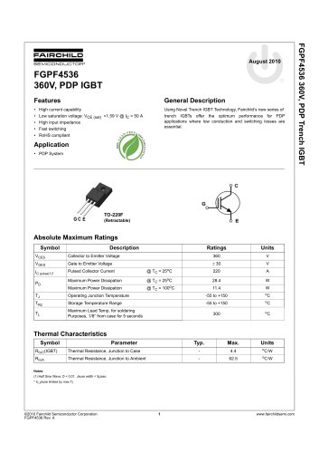 FGPF4536 360V, PDP IGBT
8 Pages
 FSAR001B AC-DC Linear Regulator
12 Pages
 Fairchild - Power solutions
52 Pages


- Position transducer
- Wireless module
- Potentiometer
- Onsemi transistor
- Industrial position sensor
- Onsemi switching transistor
- Angular position sensor
- Motor driver
- Onsemi bipolar transistor
- Digital position sensor
- DC motor motor driver
- Mechanical position sensor
- DRAM memory module
- Control potentiometer
- Signal preamplifier
- CMOS image sensor
- Applications preamplifier
- IGBT transistor
- Onsemi audio transistor
- Inductive position sensor