- Catalogs
- OnRobot ApS
- 2FGP20
2FGP20
1 /13Pages

2FGP20
1 /13Pages
Catalog excerpts
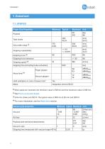
1. Datasheet 1.1. 2FGP20 Finger Grip Properties Minimum Typical Maximum Unit Total stroke Grip width range (1) Gripping repeatability Gripping force tolerance Gripping time (including brake activation) Finger gripper [dB(A)]Leq [dB(A)]Max Vacuum gripper [dB(A)]Leq [dB(A)]Max Hold workpiece in case of power loss? Integrated, electric BLDC (1) When pads are mounted, the minimum value is 158 mm and the maximum value is 418 mm. (2) See Force vs Current Graph (3) At 6 mm stroke and 150 N. The typical value is 900 ms at 20 mm and 200 N. (4) For more information, see the Noise level section. Vacuum...
Open the catalog to page 2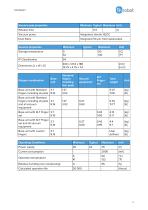
Vacuum grip properties Minimum Typical Maximum Unit Release time Vacuum pump Integrated, electric BLDC Dust filters Integrated 50 µm, field replaceable General properties Storage temperature Standard fingers including four pads Vacuum equipment Total weight Base unit with Standard 3.7 fingers including all pads 8.16 Base unit with Standard fingers including all pads 3.7 and all vacuum 8.16 equipment Base unit with KLT Finger 3.7 set 8.16 Base unit with KLT Finger 3.7 set and all vacuum 8.16 equipment Base unit with custom fingers User defined Gripper combination Base unit Operating Conditions...
Open the catalog to page 3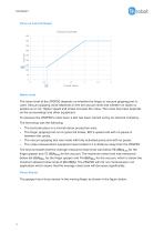
Force vs Current Graph Noise Level The noise level of the 2FGP20 depends on whether the finger or vacuum gripping part is used. Vacuum gripping noise depends on the set vacuum level and whether an object is picked up or not. Higher speed and stroke increase the noise. The noise level also depends on the surroundings and other equipment. To measure the 2FGP20’s noise level, a test has been carried out by an external company. The test setup was the following: • • • • The test took place in a normal indoor production area. The finger gripping test ran 4 cycles full stroke, 100 % speed and with no...
Open the catalog to page 4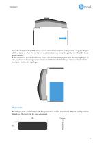
Consider the presence of the force sensor when the workpiece is aligned by using the fingers of the gripper or when the workpiece is picked sideways since the gravity can affect the force measurement. If the workpiece is picked sideways, make sure to orient the gripper with the moving finger on top, as shown in the image below. Also ensure that the bottom finger makes contact with the workpiece before the top finger. Finger pads Four finger pads are provided with the gripper and can be mounted in different configurations to achieve the best grip for your workpiece.
Open the catalog to page 5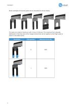
Some examples of how the pads can be mounted are shown below. The pads are made of aluminum with a cover of silicone. The maximum force (equally distributed in the blue area of the images below) that can be applied to the finger pads is shown in the table below. Illustration
Open the catalog to page 6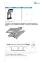
Finger set for KLT boxes The Finger set for KLT boxes enhances the grip stability for KLT containers and other open box types with groove. The fingertips can be adjusted to the open slots on the large variants of boxes. These fingers are accessories and need to be purchased separately. To purchase these fingers, please contact the vendor from where the gripper has been purchased. • See examples with 400 x 300 mm and 600 x 400 KLT boxes:
Open the catalog to page 8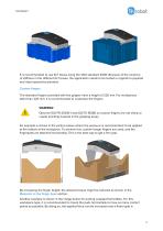
It is recommended to use KLT boxes using the VDA standard 4500. Because of the variance of stiffness in the different KLT boxes, the application needs to be tested in regards to payload and robot speed/acceleration. Custom fingers The standard fingers provided with the gripper have a height of 220 mm. For workpieces taller than 220 mm, it is recommended to customize the fingers. WARNING: Observe ISO/TR 20218-1 and ISO/TS 15066 so custom fingers are not sharp or create pinching hazards in the gripping areas. An example is shown in the picture below where the pressure is recommended to be applied...
Open the catalog to page 9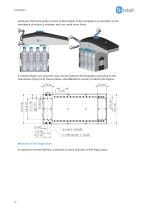
achieved. Place the pads as close to the bottom of the workpiece as possible, so the workpiece structure is stronger and can resist more force. If custom fingers are required, they can be made to fit the gripper according to the dimensions (mm) [inch] shown below. Use M6x10mm screws to attach the fingers. Moments in the finger base A maximum moment 80 Nm is allowed on each direction of the finger base.
Open the catalog to page 10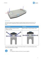
Vacuum cups The vacuum solution has been designed to handle interlayer sheets and similar items. The two most common configurations with the delivered bracket and vacuum cups are shown below. Square Shape Better for cardboard interlayer sheets or multiple layer paper Better for paper or similar interlayer sheets The provided tube length is adequate for the Square Shape. For using the Row Shape, please cut two of the tubes to 83 mm length. NOTE: It is important to always use the four air sources together.
Open the catalog to page 11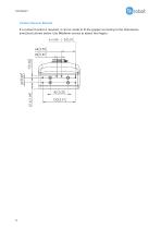
Custom Vacuum Bracket If a custom bracket is required, it can be made to fit the gripper according to the dimensions (mm) [inch] shown below. Use M6x6mm screws to attach the fingers.
Open the catalog to page 12All OnRobot ApS catalogs and technical brochures
 3FG15
3FG1511 Pages
 GECKO SP1/3/5
6 Pages
 MG10
MG109 Pages
 2FG7
2FG79 Pages
 RG2-FT
8 Pages
 RG6
RG67 Pages
 OnRobot A/S
6 Pages
 GECKO GRIPPER V1.0
5 Pages
 GECKO GRIPPER
2 Pages
 QUICK CHANGER
2 Pages
 VG10 VACUUM GRIPPER
2 Pages
 RG2-FT GRIPPER
2 Pages
 RG2 Gripper
7 Pages
 RG6 Gripper
6 Pages
 HEX-E/H QC
6 Pages
 VG10
VG1012 Pages
 RG2
RG26 Pages


- Sanding machine
- Lifting system
- Electric screwdriver
- Parallel gripper
- 2-jaw gripper
- Electric sander
- Straight electric screwdriver
- Torque transducer
- Industrial robot gripper
- Compact gripper
- Tool changer
- Handling gripper
- Dynamic torque sensor
- Cordless electric screwdriver
- Magnetic gripper
- Robotic tool changer
- 3-jaw gripper
- Angular gripper
- Soft gripper
- Electric gripper