


FILTERS

FILTERS
This section details the indicators for detecting clogs in suction lines, including adaptors for 1/4” BSP connections used in complete filters with suction by-pass. Part numbers and ordering examples are provided.
Specifications for vacuum gauges and switches are outlined, including maximum feeder voltage, resistive and inductive loads, and protection ratings (IP 65) for models VE2 and VE3.
Instructions for ordering complete filters and replacement elements are given, listing nominal sizes, filtration elements, and materials like resin-treated cellulose and inorganic fibers with filtration ratings (e.g., 10 µm, 25 µm).
The AFR series is designed for suction and return lines with flow rates up to 180 L/min, made from advanced materials for efficiency and durability, complying with ISO standards for quality and hydraulic fluid compatibility.
Details on materials used in filter elements and housings, including galvanized sheet iron and Aisi 304 mesh, and the construction of by-pass valves and seals.
Specifications for maximum working pressure, test pressure, and temperature range are provided, with compatibility for various mineral oils as per ISO 6743/4 standards.
Flow rates are calculated to maintain specific pressure drops for return and suction lines using mineral oil with a kinematic viscosity of 30 cSt.
Pressure drops for AFR series filters are outlined, with return lines set at ≤40,000 Pa (0.4 bar) and suction lines at ≤10,000 Pa (0.1 bar), based on mineral oil with a kinematic viscosity of 30 cSt and a density of 860 kg/m³.
Pressure drops are calculated by summing the pressure drop of the filter housing and element, with graphical data provided for pressure drops in both housing and elements.
For AFR series 60, 100, and 180, recommended flow rates for various filter elements are listed, detailing suction and return flows in liters per minute (l/min) and corresponding weight in kilograms (kg).
Technical data for clogging indicators in return lines, specifying pressure gauges and switches with various electrical contacts and settings.
Graphs illustrate the relationship between flow rates and pressure drops for different filter elements and housing types, adhering to ISO 3968 standards.
- Maximum working pressure: 10 bar
- Maximum test pressure: 18 bar
- Suction by-pass valve calibrated to 0.25 bar ± 10%
- Return by-pass valve calibrated to 1.7 bar ± 10%
- Working temperature range: -25°C to +95°C
- Compatibility with hydraulic oils as per ISO 2943
- Filtrating elements collapse pressure according to ISO 2941
- Threaded connections according to UNI 388
- Filter head made of aluminium UNI 5076 alloy
- Types A and B: Micropaper treated with resin, filtration ratios of 10 and 25 microns ßx≥2
- Type C: Steel with filtration ratio of 60 microns
- Type E: Brass mesh with filtration ratio of 125 microns
- Filtration efficiency tested as per ISO 4572
- PV1: Gauge with pressure range from 0 to 12 bar
- VV1: Suction line gauge scale to 76 cm Hg
- PE1: Pressure switch with normally open electrical contacts, pressure setting 1.3 bar ± 10%
- PE2: Pressure switch with normally closed electrical contacts, pressure setting 1.3 bar ± 10%
- VE1: Vacuum switch with normally open electrical contacts, set at 0.2 bar ± 10%
- DV131 and DV130: Differential visual indicators calibrated at 1.3 bar ± 10%
- DE131 and DE130: Differential visual electrical indicators calibrated at 1.3 bar ± 10%
- PE3: Membrane pressure switch with pressure setting 1.3 bar ± 10%
- Pressure drop of the complete filter is calculated by adding the pressure drop of the housing to that of the filter element.
- Pressure drops in the housing are proportional to the mass density of the oil used, typically mineral oil with a mass density of 860 kg/m³.
- Pressure drops in the filter elements are proportional to the kinematic viscosity of the oil, typically 30 cSt.
- Spin-on filters are suitable for both suction and return lines in hydraulic and lubrication systems.
- Available with port tappings from 3/4” to 1.1/2” BSP, with larger sizes available with SAE ports.
- Spin-on replacement elements can be supplied standard or with a safety feature to prevent oil spillage during replacement.
- Filter heads are compatible with both European and American standard cartridge elements.
The document discusses the calculation and implications of pressure drops (Δp) in filter systems. The total pressure drop is the sum of the pressure drops across the filter housing and the filter element at a given flow rate. Ideally, this should not exceed 0.5 bar (7.3 psi) and should never exceed one-third of the by-pass valve's set value. The pressure drop is influenced by oil viscosity, which is roughly proportional.
Clogging Indicators
Pressure drop through the filter increases during operation, and the filter element should be replaced when indicated, before reaching the by-pass valve setting. Cold start conditions may cause false alarms due to higher oil viscosity.
Technical and Electrical Data
The document provides technical specifications for pressure gauges and switches, including maximum feeder voltage, resistive and inductive loads, and protection ratings. It also includes part numbers and descriptions for various components.
Filter Codification
Details on filter codification are provided, including nominal sizes, filter element types, and seal materials. The document notes that OMT reserves the right to modify specifications without notice.
1. Filtration Elements: Various materials and filtration degrees are specified, including micropaper, steel mesh, and micro inorganic fibers with filtration degrees ranging from 3 to 60 microns.
2. Pressure Ratings: Maximum working pressure is 110 bar, with a test pressure of 220 bar. Differential collapse pressure is 20 bar according to ISO 2941.
3. Temperature Range: Operating temperature ranges from -25°C to +110°C.
4. Compatibility: Compatible with mineral oils as per ISO 6743/4 and tested for material compatibility according to ISO 2943.
5. Construction: Filter head and body are made from aluminum die-casting, with glass-reinforced nylon for the filter bowl and cover.
Procedures and Standards
1. Manufacturing Compliance: Filters are produced in accordance with ISO 2942.
2. Filtration Efficiency: Multi-pass test conducted as per ISO 4572.
3. Pressure Drop: Pressure drop calculations are provided for both the housing and filter elements, with reference to ISO 3968.
Recommendations and Best Practices
1. By-pass Valve: Set to 6 bar, ensuring protection against excessive pressure.
2. Installation: Suitable for use in pressure lines with flow rates up to 6 L/min, with options for by-pass valve inclusion.
Technical Data
1. Materials: Nitrile (Buna-N) and Fluoroelastomer (Viton) seals are used, with options for different filtration materials.
2. Indicators: Visual and electrical indicators are available, with options for "Reed" contacts.
Ordering Information
1. Filters and replacement elements can be ordered with specific filtration degrees and materials, with detailed part numbers provided for complete filters and replacement elements.
The document outlines the specifications for hydraulic filters, specifically the MHP220 and HPB series. The MHP220 series is compatible with mineral oils and operates within a temperature range of -20°C to +95°C. It has a maximum working pressure of 280 bar and a by-pass valve set at 5 bar ±10%. The HPB series is suitable for pressure lines up to 315 bar, with a filtration degree up to 3 microns and a maximum nominal flow of 90 L/min.
The filter housing is made of brass, with gaskets available in Buna-N or Viton. Filter elements are constructed from inorganic fibre, resin-treated paper, or steel wire mesh. Support structures include galvanized steel with epoxy treatment and zinc-treated steel for internal cores and end caps.
The filters are tested according to various ISO standards, including ISO 2941 for collapse/burst pressure resistance, ISO 2942 for fabrication integrity, ISO 2943 for material compatibility, ISO 3723 for end load tests, ISO 3724 for flow fatigue characteristics, ISO 3968 for pressure drop evaluation, and ISO 16889 for filtration performance.
Filtration elements are available in different materials and filtration degrees. Inorganic fibre elements have a filtration ratio βx≥200, equivalent to 99.5% efficiency. Resin-treated paper and wire mesh elements have a filtration ratio βx≥2, equivalent to 50% efficiency.
The pressure drop of the complete filter is calculated by adding the housing pressure drop to that of the filter element, based on the working flow rate. The document provides guidelines for selecting filters to ensure the pressure drop remains within acceptable limits.
The document includes detailed instructions on how to order complete filters and replacement elements, specifying the series, filtration degree, filter media, and optional features like by-pass valves and seal materials.
The HMM series medium pressure filters are designed for pressures up to 22,000,000 Pa (220 bar) for the HMM28 model and 32,000,000 Pa (320 bar) for the HMM42 model. They support nominal flow rates up to 170 L/min with options for threaded or flanged connections. The filter elements are constructed from advanced materials to ensure high filtration efficiency and durability.
Modular Design
The modular construction of the HMM series allows customers to select configurations that best meet their needs. This flexibility is a key feature of the series.
Materials
The HMM28 model uses aluminum for the head, while the HMM42 uses cast iron. Both models use steel for the bowl, with seals available in Nitrilic (Buna-N) or Fluoroelastomer (Viton). The by-pass and reverse flow valves are made of brass.
Operating Conditions
The filters are compatible with mineral oils as per ISO 6743/4 standards. The maximum operating temperature ranges from -20 to +95°C. The burst pressure for the HMM28 is 66,000,000 Pa (660 bar) and for the HMM42 is 96,000,000 Pa (960 bar).
Pressure Drops
Pressure drops are calculated by adding the pressure drop of the housing to that of the filter element. The pressure drop is proportional to the mass density and kinematic viscosity of the oil used.
Recommended Flows
Flow rates are calculated to maintain a pressure drop of ≤ 120,000 Pa (1.2 bar) with mineral oil having a kinematic viscosity of 30 cSt and a density of 860 kg/m³.
Ordering Information
Filters can be ordered with various configurations, including different filtration elements, seals, and by-pass valve settings. Options for reverse flow valves and specific configurations for filters with or without by-pass are available.
Additional Features
The document also details the availability of differential indicators and reverse flow valves for specific models, enhancing the functionality and monitoring capabilities of the filters.
- Maximum Operating Pressure: 315 bar
- Burst Pressure: 950 bar
- Connection Ports: 1/2” BSP, 3/4” BSP, M22x1.5 (other options available on request)
- Materials: Cast iron head, steel container, NBR seals (FKM available on request)
- By-Pass Valve: Opens at 6 bar ± 10%
- Filter Element Media: Microfiber, cellulose, and wire mesh
- Collapse Pressure: 20 bar or 210 bar
- Working Temperature Range: -25°C to +110°C
- Fluid Compatibility: Compatible with HH-HM-HR-HV-HG oils
- Ensure the filter operates within specified pressure, temperature, and fluid compatibility.
- Replace the filter element when the clogging indicator signals an alarm.
- Perform maintenance only when the system is off and ensure no residual pressure is present.
- Use OMT cartridges for replacements and check part numbers.
- Replace seals if necessary, lubricate threads, and screw carefully.
The document outlines the specifications for high-pressure filters in the HPM series, capable of handling pressures up to 42,000,000 Pa (420 bar). The filters are available in three sizes with nominal flow rates up to 400 L/min and can be configured with either threaded or flanged connections. The filter elements are constructed from advanced materials to ensure high filtration efficiency and durability.
Materials
The materials used in the construction of the filters include cast iron for the head, steel or cast iron for the bowl, Buna-N or Viton for the seals, and brass for the by-pass and reverse flow valves.
Operating Conditions
The filters are designed to operate within a temperature range of -20 to +95°C. The maximum working pressure is 42,000,000 Pa (420 bar), with a testing pressure of 63,000,000 Pa (630 bar) and a collapse pressure of 126,000,000 Pa (1260 bar). The by-pass valve setting pressure is 6 bar ±10%. The filters are compatible with mineral oils such as HH, HM, HR, HV, and HG according to ISO 6743/4.
Recommended Flows and Connections
The document provides detailed information on recommended flows for different series (X and Y) and the corresponding threaded and flanged connections. The flows are calculated to achieve a pressure drop of ≤ 120,000 Pa (1.2 bar) with mineral oil having a kinematic viscosity of 30 cSt and a density of 860 kg/m³.
Interchangeability and Reverse Flow Valve
The OMT filter elements in the CHP series are interchangeable with Pall filter elements. The document provides part numbers for both OMT and Pall elements. A reverse flow valve is available for specific HPM models.
Pressure Drops
The pressure drop for the complete filter is the sum of the pressure drop in the housing and the filter element. The document includes graphs showing pressure drops for different flow rates and filter elements, based on the use of mineral oil with specific density and viscosity.
The document describes air filters designed for mounting on oil tanks to filter air. These filters are available with BSP threaded connections and feature replaceable elements that can be regenerated in a velvet net with a standard filtration grade of 40 microns. The filters are also used in the suction of compressors and engines.
Product Variants
The document lists various series and types of air filters, including TSA and CSA series, with specific dimensions and connection types. The TSA series includes models like TSA3-14, TSA50-14, and TSA70-12, among others, with detailed dimensions and connection sizes. The CSA series includes models like CSA05 and CSA10, with dimensions and filtration elements specified.
Ordering Information
The document provides examples of ordering codes for different series and types of air filters, specifying dimensions and filtration elements. For instance, the CSA series uses codes like CSA 05 A - S, with dimensions and filtration elements detailed for each model.
Quality Assurance
OMT Group S.p.A. is certified under the ISO 9001:2015 Quality Management System standard, covering the design and manufacture of heat exchangers, hydraulic components, and related systems. The certificate is valid from 31 October 2021 to 30 October 2024.
Recommendations
Customers are advised to regularly check the catalog contents for updates, as changes may occur without prior notice. The latest version of the catalog can be accessed on the OMT Group website.
Catalog excerpts

FILTRI FILTERS
Open the catalog to page 1
Portaci nel futuro, saremo al tuo fianco nelle tue prossime sfide. Trust it. Take us to the future and we will stand by your side as you face new challenges. Trust it.
Open the catalog to page 2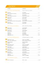
INDEX AZIENDA SUCTION FILTERS AFI SERIES Filtri in aspirazione e sul ritorno Suction and return filters Filtri in aspirazione e sul ritorno Suction and return filters SERIE OMTI OMTI SERIES Filtri spin-on Spin-on filters SERIE SF-SP SF-SP SERIES Filtri in aspirazione immersi / Serie spaccalegna Suction strainers / For log splitters Suction filters RETURN FILTERS OMTF SERIES Return filters SERIE OMTP OMTP SERIES Return filters SERIE OMTF PRESSURE FILTERS APM 110 bar SERIES Filtri in linea a media pressione Filtri alta pressione High pressure filters Filtri media pressione Medium pressure filters...
Open the catalog to page 3
PROGETT AZIONE PROJECTS Il moderno e qualificato ufficio tecnico progetta e sviluppa nuovi prodotti ed esegue progetti speciali su richiesta del cliente. The modern and qualified technical Department is skilled in designing and develop new products and it is ready to support every customer’s request with special solutions. QUALITÀ QUALITY È un punto di forza di OMT Group e viene costantemente controllata nella moderna e attrezzata sala prove. OMT Group è conforme ai requisiti del Sistema Gestione Qualità ISO 9001:2015. Is a strong point of OMT Group and it is constantly monitored in the modern...
Open the catalog to page 4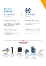
DALL’ ESPERIENZA From expertise OMT Group è una realtà dinamica e all'avanguardia, forte di un'esperienza di oltre 55 anni nel settore dell'oleodinamica. L'innovazione presuppone non solo l'aumento di spazi, il potenziamento degli impianti e dei macchinari, ma un programma da realizzare con un gruppo unico, coeso, in grado di rispondere alle richieste di un mercato in continua evoluzione. Nel 2022 OMT Group incorpora OMT e LUEN, ne raccoglie l'esperineza e programma il cambiamento per il futuro. Innovation does not just involve changing premises and upgrading plants and machinery, but also includes...
Open the catalog to page 5
AFI è la serie di filtri particolarmente indicata per applicazioni industriali su linee di ritorno e aspirazione. Funzionando ad una pressione massima di 2.000.000 Pa (20 bar), trovano impiego anche su linee di mandata a bassa pressione. Materiali e tecnologie avanzate, impiegate per la costruzione degli elementi filtranti, consentono elevate prestazioni ed efficienza conformi alle norme ISO vigenti relative alla qualità degli stessi elementi filtranti. The AFI series is particulary suitable for industrial use, to be installed on return and suction lines. Operating at a maximum pressure of 2.000.000...
Open the catalog to page 6
FILTRI IN ASPIRAZIONE E SUL RITORNO SUCTION AND RETURN FILTER SERIES
Open the catalog to page 7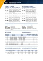
CARATTERISTICHE TECNICHE TECHNICAL DATA CARATTERISTICHE TECNICHE TECHNICAL DATA LA SERIE DI FILTRI AFI È CONFORME ALLE SEGUENTI NORME ISO: AFI FILTER SERIES IS SUITABLE TO THE FOLLOWING ISO STANDARDS: -ISO 2941 - Oleoidraulica - Elementi filtranti - Verifica della resistenza allo schiacciamento o allo scoppio -ISO 2941 - Hydraulic fluid power - Filter elements Verification of collapse / burst resistance -ISO 2942 - Oleoidraulica - Elementi filtranti - Verifica dell’integrità di fabbricazione e determinazione del punto di prima bolla -ISO 2942 - Hydraulic fluid power - Filter elements Verification...
Open the catalog to page 8
VALVOLA DI MASSIMA PRESSIONE CARATTERISTICHE TECNICHE DIRECT POPPET TYPE RELIEF TECHNICAL DATA CARATTERISTICHE TECNICHE TECHNICAL DATA MATERIALI (corpo) MATERIALS (housing) N: Nitrilica (Buna-N) V: Fluoroelastomero (viton) Materiale plastico Ottone N: Nitrile (Buna-N) V: Fluoroelastomer (viton) Plastic material Brass Valvola di by-pass Indicatore By-pass valve Indicator WORKING CONDITIONS Pressioni corpo filtro Pressione massima d’esercizio: 2.000.000 Pa (20 bar) Pressione di collaudo: 3.000.000 Pa (30 bar) Pressione di 8:05 Pagina 3 Omt_AFI:Omt_AFI 17-02-2009 scoppio: 60.000.000 Pa (60 bar)...
Open the catalog to page 9
CARATTERISTICHE DIMENSIONALI SIZE FEATURES Le portate sono state calcolate per avere una perdita di carico ∆p ≤ 60.000 Pa (0.6 bar) per i filtri sul ritorno e ∆p ≤ 5.000 Pa (0.05 bar) per i filtri in aspirazione. I valori sono stati ottenuti con olio Minerale avente viscosità cinematica 30 cSt e densità 860 kg/m3. (vedi note a pag.12) 10) Flows have been calculated just in order to obtain a pressure drop ∆p ≤ 60.000 Pa (0.6 bar) for return lines and ∆p ≤ 5.000 Pa (0.05 bar) for suction lines. The values have been obtained using mineral oil kinematic viscosity 30 cSt and 860 kg/m3 density. 12)...
Open the catalog to page 10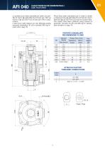
CARATTERISTICHE DIMENSIONALI SIZE FEATURES Le portate sono state calcolate per avere una perdita di carico ∆p ≤ 60.000 Pa (0.6 bar) per i filtri sul ritorno e ∆p ≤ 5.000 Pa (0.05 bar) per i filtri in aspirazione. I valori sono stati ottenuti con olio Minerale avente viscosità cinematica 30 cSt e densità 860 kg/m3. (vedi note a pag.13) 10) Flows have been calculated just in order to obtain a pressure drop ∆p ≤ 60.000 Pa (0.6 bar) for return lines and ∆p ≤ 5.000 Pa (0.05 bar) for suction lines. The values have been obtained using mineral oil kinematic viscosity 30 cSt and 860 kg/m3 density. 13)...
Open the catalog to page 11
AFI 100 CARATTERISTICHE DIMENSIONALI SIZE FEATURES Le portate sono state calcolate per avere una perdita di carico ∆p ≤ 60.000 Pa (0.6 bar) per i filtri sul ritorno e ∆p ≤ 5.000 Pa (0.05 bar) per i filtri in aspirazione. I valori sono stati ottenuti con olio Minerale avente viscosità cinematica 30 cSt e densità 860 kg/m3. (vedi note a pag. 14) 10) Flows have been calculated just in order to obtain a pressure drop ∆p ≤ 60.000 Pa (0.6 bar) for return lines and ∆p ≤ 5.000 Pa (0.05 bar) for suction lines. The values have been obtained using mineral oil kinematic viscosity 30 cSt and 860 kg/m3 density....
Open the catalog to page 12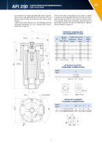
CARATTERISTICHE DIMENSIONALI SIZE FEATURES Le portate sono state calcolate per avere una perdita di carico ∆p ≤ 60.000 Pa (0.6 bar) per i filtri sul ritorno e ∆p ≤ 5.000 Pa (0.05 bar) per i filtri in aspirazione. I valori sono stati ottenuti con olio Minerale avente viscosità cinematica 30 cSt e densità 860 kg/m3. (vedi note a pag.15) 10) Flows have been calculated just in order to obtain a pressure drop ∆p ≤ 60.000 Pa (0.6 bar) for return lines and ∆p ≤ 5.000 Pa (0.05 bar) for suction lines. The values have been obtained using mineral oil kinematic viscosity 30 cSt and 860 Kg/m3 density. 15)...
Open the catalog to page 13All OMT Group catalogs and technical brochures
 HEAT EXCHANGERS
176 Pages
 COMPONENTS AND ACCESSORIES
142 Pages
 ACCUMULATORS
44 Pages

