XS2
1 /29Pages

XS2
1 /29Pages
Catalog excerpts
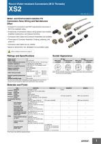
Socket Appearance Water- and Environment-resistive FA Connectors Save Wiring and Maintenance Effort • Compact FA connectors meet IP67 requirements and ensure a 94V-0 fire retardant rating. • A wide array of connectors makes a wiring system more modular, simplifies maintenance, and reduces downtime. • Connectors with Cables and Connector Assemblies are available. • Three types of Connector Assembly: Crimping, soldering, and screw-on. • Connectors with Cables are UL certified. • Based on IEC61076-2-101 (IEC60947-5-2) and NECA 4202. Refer to Safety Precautions on page 21. *Use the robot cable within a temperature range between 0°C and 70°C to prevent the wires inside the cable from being broken when bending it.
Open the catalog to page 1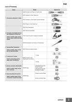
XS2 List of Products Name XS2W Sockets and Plugs on Cable Ends XS2F Sockets on One Cable End 1. Connectors attached to Cable XS2F Sockets on One Cable End with Indicator XS2H Plugs on One Cable End XS2G Plug Assemblies XS2C Socket Assemblies 2. Connector Assemblies (Crimping, Soldering, or Screw-on) XY2F Crimp Tool (for Crimping Connectors) Used to enable using connectors for sensor cables and relay cables. XW4Z Screwdriver (for Screw-on Connectors) 3. Terminal Box Connectors Used to enable using connectors for terminal boxes. T-Joints 4. T-Joints and Y-Joints Used for branching and for daisy-chain...
Open the catalog to page 2
Sockets and Plugs on Cable Ends Model Number Legend Use this model number legend to identify products from their model number. When ordering, use a model number from the table in Ordering Information. 1. Type W: Connectors connected to cable, socket and plug on cable ends 2. AC/DC (Mating Section Form) D: For DC 3. Connector Poles 4: 4 poles 5: 5 poles 4. Contact Plating 2: 0.4-|j.m gold plating 5. Cable Connection Direction 1: Straight/straight 2: L-shaped/L-shaped 3: Straight (Socket)/L-shaped (Plug) 4: L-shaped (Socket)/straight (Plug) 6. Cable Length A: 0.3 m (straight/straight only) B: 0.5...
Open the catalog to page 3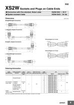
Straight/Straight Connectors Wiring Diagram for 4 Cores Wiring Diagram for 5 Cores Cable lead colors 1 Brown 2 White SBlue Black (DC) Ordering Information Cable Specifications Note: Ask your OMRON representative about other cable lengths, and about 5-core cables.
Open the catalog to page 4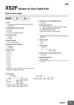
Socket on One Cable End Model Number Legend Use this model number legend to identify products from their model number. When ordering, use a model number from the table in Ordering Information. 1. Type F: Connector connected to cable, socket on one cable end 2. AC/DC (Mating Section Form) A: For AC D: For DC E: For DC, stainless steel lock 4. Contact Plating 2: 0.4-^m gold plating 5. Cable Connection Direction 1: Straight 2: L-shaped 6. Cable Length A: 0.3 m B: 0.5 m C: 1 m D: 2 m E: 3 m F: 4 m G: 5 m H: 7 m J: 1 0 m K: 15 m L: 20 m Only the 2 m (D), 5 m (G) and 10 m (J) cables are available for...
Open the catalog to page 5
XS2F Sockets on One Cable End ● Connectors with Fire-retardant, Robot Cable XS2F-@42@-@@0-F ● Non-polar DC Connectors with Standard Cable XS2F-@42@-@@0 ● E2E models with conventional connector pin with Fire-retardant, Robot Cable XS2F-D42@-@D0 ● Heart-resistant Cable up to 105°C XS2F-E42@-@80-E ● Spatter-resistant Cables XS2F-D421-@80-SA Dimensions Wiring Diagram Two-core model Fire-retardant, Robot cable Spatter-resistant Cables* Heat-resistant Cables up to 105°C * Standard cable (non-polar DC) Fire-retardant, Robot cable (E2E models with conventional connector pin) Cable lead colors Cable lead...
Open the catalog to page 6
Ordering Information Cable Specifications Fire-retardant, Robot cable Standard cable (non-polar) Fire-retardant, Robot cable (E2E models with conventional connector pin) Spatter-resistant Cables Minimum order Note: Ask your OMRON representative about other cable lengths. *The heat-resistant fixture material is SUS316L stainless steel without surface treatment.
Open the catalog to page 7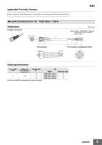
Applicable Proximity Sensors Refer to page the E2E Datasheet for information on connecting to E2E Proximity Sensors Dimensions Straight Connectors Note: Use the XS2H-D521-DG0-A in combination with the XS2F-D521-DG0-A. Pin Arrangements (Engagement Side) Cable lead colors Ordering Information No. of cable cores Note: Ask your OMRON representative about other cable lengths.
Open the catalog to page 8
Sockets on One Cable End with IndicatorModel Number LegendXS2F-M12 PVC □ 12 3 4 1. Type F: Connector connected to cable, sockets on one cable end 2. Mating Section Form M12: M12 4. Connector Poles 3: 3 poles 4: 4 poles 5. Cable Connection Direction A: L-shaped 10: 10 m 7. Applicable Sensors P: PNP N: NPN 8. With indicator LED: With indicator Dimensions Wiring Diagram 4 o- YELLOW GREEN —O BLACK YELLOW GREEN 3 - BLUE -o + BROWN -o WHITE -o BLACK Cable Specifications Cable connection direction Cable core cross-sectional area (mm2) Cable length (m) Minimum order
Open the catalog to page 9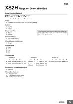
Ao^n Plugs on One Cable End Model Number Legend xs2H-nn2i-nnoco 1 2345 678 9 1. Type H: Connector connected to cable, plug on one cable end Using this model number legend to identify products from their model number. When ordering, use a model number from the table in Ordering Information. 4. Contact Plating 2: 0.4-pm gold plating 8: Brown White Blue Black (for DC) 9: Brown White Blue Black (for AC) B: --- --- Brown Blue (for AC) C: Brown --- Blue Black(for DC) G: Brown White Blue Black Gray 8. Connectors on One End/Both Ends 0: One end 9. Cable Specifications A: Standard cable...
Open the catalog to page 10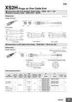
XS2H Plugs on One Cable End • Connectors with Fire-retardant, Robot Cable XS2H-@421-@@0-F • Spatter-resistant Cable XS2H-D421-@80-SA (Unit: mm) Dimensions Straight Connectors Cable lead colors Cable lead colors Brown White Blue Black (DC/AC) Four-core Model • Connectors on DC Cable (Five Poles) XS2H-D521-@G0-A (for DC) (Unit: mm) Dimensions Straight Connectors Note: Use the XS2F-D521-DG0-A in combination with the XS2H-D521-□G0-A. Pin Arrangements (Engagement Side) Black —Gray Five-core Model Ordering Information Cable Specifications
Open the catalog to page 11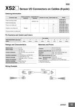
Sensor I/O Connectors on Cables (8-pole) Ordering Information Wiring Example Relay box, In-panel terminal block
Open the catalog to page 12All OMRON catalogs and technical brochures
 D4F
D4F8 Pages
 D4GS-N
11 Pages
 E4E2
E4E25 Pages
 Fiber SensorBest Selection Catalog
104 Pages
 Fiber Unit E32-LT/LD
4 Pages
 G9SE Series
20 Pages
 NX-SL/SI/SO
20 Pages
 G9SP
G9SP28 Pages
 G9SX-SM
24 Pages
 G9SX-SM/LM
9 Pages
 G9SX/G9SX-GS
49 Pages
 G9SX-LM
28 Pages
 G9SB
G9SB10 Pages
 G9SA
G9SA16 Pages
 DST1 Series
5 Pages
 WS02-CFSC1-E
3 Pages
 G9SA-300-SC
9 Pages
 K8AK-AS
12 Pages
 K8AK-AW
16 Pages
 K8AK-VS
12 Pages
 K8AK-VW
12 Pages
 K8AK-PH
12 Pages
 K8DS-PH
12 Pages
 K8AK-PM
16 Pages
 K8DS-PM
12 Pages
 K8AK-PA
12 Pages
 K8DS-PA
12 Pages
 K8AK-PW
12 Pages
 K8DS-PU
12 Pages
 K8DS-PZ
12 Pages
 K8AK-TS/PT
12 Pages
 K8AK-LS
12 Pages
 K8AK-TH
12 Pages
 K2CM
K2CM16 Pages
 SE
SE15 Pages
 SAO
SAO13 Pages
 APR-S
APR-S6 Pages
 XS5
XS525 Pages
 F92A
F92A4 Pages
 GLS
GLS3 Pages
 TL-L
TL-L5 Pages
 V680 series
68 Pages
 V680S Series
68 Pages
 MY
MY35 Pages
 E3NC-L/-S
16 Pages
 61F-GPN-BT / -BC
5 Pages
 NE1A-SCPU Series
8 Pages
![NE1A-SCPU0[]-EIP](https://img.directindustry.com/pdf/repository_di/15954/ne1a-scpu0-eip-616667_1mg.jpg) NE1A-SCPU0[]-EIP
NE1A-SCPU0[]-EIP8 Pages
 NE0A-SCPU01
6 Pages
 LY
LY14 Pages
![G2R-[]-S](https://img.directindustry.com/pdf/repository_di/15954/g2r-s-616653_1mg.jpg) G2R-[]-S
G2R-[]-S11 Pages
 G7T
G7T7 Pages
 G2A
G2A9 Pages
 G2A-434
7 Pages
 G2AK
G2AK7 Pages
 MK-S
MK-S9 Pages
 MK-S(X)
12 Pages
 MM
MM17 Pages
 MMK
MMK14 Pages
 G4Q
G4Q6 Pages
 G7Z
G7Z9 Pages
 G7J
G7J10 Pages
 E4B
E4B12 Pages
 E4A-3K
9 Pages
 E4C-UDA
5 Pages
 E6H-C
E6H-C5 Pages
 E6F-C
E6F-C5 Pages
 E6D-C
E6D-C5 Pages
 E6B2-C
5 Pages
 E6A2-C
5 Pages
 NL
NL8 Pages
 VB
VB5 Pages
 SC
SC5 Pages
 D5F
D5F5 Pages
 D5A
D5A8 Pages
 E3S-GS3E4
3 Pages
 E3S-R
E3S-R11 Pages
 E3S-A
E3S-A21 Pages
 E3S-CL
9 Pages
 E3ZM-C
14 Pages
 E3T Data Sheet
26 Pages
 E3T Series
6 Pages
 G5 Series
59 Pages
 Sysmac Catalog
410 Pages
 VT-X700
6 Pages
 E5AC-T
8 Pages
 CP1
CP112 Pages
 CP1E
CP1E12 Pages
 MS4800
40 Pages
 VC-DL100
6 Pages
 FZ4 Series
42 Pages
 ZG2
ZG216 Pages
 ZS Series
32 Pages
 ZW Series
24 Pages
 E9NC-T
2 Pages
 Vision System FH series
54 Pages
 CompoNet
28 Pages
 F3SJ Series Safety Light Curtain
108 Pages
 Code Reader/OCR
24 Pages
 Fiber Sensor Best Selection Catalog
100 Pages
 Portable Multi-logger ZR-RX70
12 Pages
 Air Particle Sensor ZN-PD-S
2 Pages
 NT series
18 Pages
 Round Water-resistant Connectors
31 Pages
 Safety Controller G9SP
28 Pages
 E3FA PHOTOELECTRIC SENSORS
24 Pages
 Switch Mode Power Supply S8VK-G
22 Pages
 Data Logger ZR-RX Series
12 Pages
 Programmable Terminals NS Series
57 Pages
 DeviceNet Safety System
30 Pages
 Switching Power Supplies
16 Pages
 Photomicro Sensors
7 Pages
 Displacement Sensors
4 Pages
 R87F / R87T AC Axial Fans
28 Pages
 H8PS Cam Positioner
32 Pages
 OS32C Safety Laser Scanner
24 Pages
 FQ Vision Sensor
17 Pages
 ZN-PD Air Particle Sensor
16 Pages
 S8EX Switch Mode Power Supply
24 Pages
 CP1L CP series CP1L CPU Unit
36 Pages
 E2EF
E2EF8 Pages
 FQ2 Smart camera
24 Pages


Archived catalogs
 REGULATION SOLUTIONS
24 Pages
 Sensor Accessories
38 Pages
 SMART REMOTE I/O
12 Pages
 SAFETY APPLICATION HANDBOOK
55 Pages
 Vision Systems
20 Pages
- SARRALLE industrial robot
- Digital I/O
- Single-pole switch
- IO module
- Propeller fan
- Push-button switch
- SARRALLE air circulation fan
- Digital temperature control
- SARRALLE industrial fan
- Terminal box
- Switching relay
- Analog I/O
- SARRALLE digital indicator
- Digital IO module
- SARRALLE handling robot
- SARRALLE 3D software
- AC fan
- SARRALLE interface software
- SARRALLE panel-mount indicator
- SARRALLE simulation software