UM, MC3 Safety Mat/Safety Mat Controller
1 /19Pages

UM, MC3 Safety Mat/Safety Mat Controller
1 /19Pages
Catalog excerpts

Safety Mat / Safety Mat Controller UM/MC3 Stay one step ahead in safety
Open the catalog to page 1
S a fe t y M a t s a r e s a fe t y m e a s u r e s t h a t t a k e i n t o c o n s i d e r a t i o n u s a b i l i t y i n t h e wo r k p l a c e . OMRON Safety Mats continue on their unique path of evolution. On-site safety can be fur ther improved by placing Safety Mats precisely in areas where other sensors do not reach. The tion. Safety Mats elicit the full power of every location and are suitable for any application. Reduce labor associated with cumbersome layout, installation and maintenance The UM system takes the site into con m consideration n Connectors make wiring simple 1 Cables...
Open the catalog to page 2
Safety Mat/Safety Mat Controller UM/MC3 New Safety Mat That Is Easy to Install and Maintain • Simple connection allows multiple mats to be joined together. • A wide variety of mat sizes are available. • Obtained EN1760-1 and EN ISO13849-1 (PLd/Safety Category 3) certification. • Complies with North American safety standards, including ANSI/RIA15.06-1999. Be sure to read the "Safety Precautions" on page 14. Model Number Structure Model Number Legend Safety Mat UM@@@-@-@ Base ––– – – 1 2 3 4 B 5 1. Color None : Black Y : Yellow 2. Unit of Length None : Inch M : Millimeter 3. Cable Length 5 :5m...
Open the catalog to page 3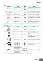
UM/MC3 Trims Appearance Name Model Remarks Ramp Trim with Yellow PVC Cover (1.22 m) UMRT4 Ramp Trim with Yellow PVC Cover (2.44 m) UMRT8 Installed on the perimeter of the Safety Mat. Each Trim is composed of two parts, an aluminum base and a PVC Cover. Possible to install cables inside. Joining Trim (1.22 m) UMJS4 Joining Trim (2.44 m) UMJS8 The Joining Trims join the Safety Mats when two or more Safety Mats are being combined. In addition to joining the Safety Mats, the Joining Trims preserve the Safety Mat's sensitivity at the joints. Aluminum Ramp Trim (2.44 m) UMAL Installed on the perimeter...
Open the catalog to page 4
UM/MC3 Specifications Ratings Safety Mat Controller Power input Item Model MC3 Power voltage 24 VDC Operating voltage range -15% to +15% of rated supply voltage Power consumption * 3 W max. * Power consumption of loads is not included. Switch Item Model MC3 Rated load 6 A at 230 VAC/6 A at 24 VDC (resistive load) 5 A at 230 VAC (AC15)/2 A at 24 VDC (DC13) (inductive load) Maximum rated voltage 250 VAC/24 VDC Rated carry current 6A Maximum switching capacity 1,500 VA Characteristics Safety Mat Item Model UM Detection method Pressure sensing method Detection weight 30 kg min. Maximum allowable...
Open the catalog to page 5
UM/MC3 Installation Using Trim Pieces Example 2: Using three Safety Mats Ramp Trim with Yellow PVC Cover: UMRT4/UMRT8 Secures the edges of the Safety Mats to the floor. It is composed of two parts with an aluminum base and a PVC Cover. Joining Trim: UMJS4/UMJS8 The Joining Trims join the Safety Mats when two or more Safety Mats are being combined. In addition to joining the Safety Mats, the Joining Trims preserve the Safety Mat's sensitivity at the joints. Aluminum Ramp Trim: UMAL Secures the edges of the Safety Mat to the floor. The Aluminum Ramp Trim is hollow, so cable can be routed through...
Open the catalog to page 6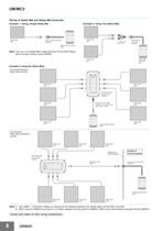
UM/MC3 Wiring of Safety Mat and Safety Mat Controller Example 1: Using a Single Safety Mat Safety Mat UM@ Example 2: Using Two Safety Mats Safety Mat UM@ Panel-mount Connector UMPMC Y Connector UM-Y-2-1 Panel-mount Connector UMPMC Safety Mat Controller MC3 Note: You can cut a Safety Mat's cable and wire it to the MC3 Safety Mat Controller without using UMPMC. Safety Mat Controller MC3 Safety Mat UM@ Example 3: Using Six Safety Mats Connecting directly to Safety Mat Controller Safety Mat UM@ Safety Mat UM@ Distribution Box (for six mats) UMDB-6 Connector with cable Socket on one cable end XS2F-D421-@80-F...
Open the catalog to page 7
UM/MC3 Connections Internal Connection Y2 X1 Y1 Power supply X2 13 23 31 41 14 24 32 42 Control Circuit M11 M12 M21 M22 Wiring of Inputs and Outputs Signal name Terminal name Power supply input Description of operation Wiring Y1, Y2 Connect the power supply plus (24 VDC) to the Y1 Power supply input terminals for MC3 terminal. Connect the power source to the Y1 and Y2 terminals. Connect the power supply minus (GND) to the Y2 terminal. M11, M12, M21, M22 To turn ON safety outputs, all the connected safety mats must have no load. Otherwise, the safety outputs will NOT turn ON. M12 Safety Mat input...
Open the catalog to page 8
UM/MC3 Dimensions (Unit: mm) Safety Mat Controller MC3 Terminal/LED arrangements Y2 Y1 X1 X2 M11 M12 M21 M22 LED (red) Lights when the safety output from the MC3 Safety Mat Controller is OFF 110 LED (green) Lights when the safety output from the MC3 Safety Mat Controller is ON 15.3 55 84 Stop Run Mat Clear LED (green) Lights when the UM Safety Mat is not being activated (i.e., when intrusion is not being detected) 13 14 23 24 31 32 41 42 98 38 75 61.2 Two, R2.2 Trims Ramp Trim with Yellow PVC Cover UMRT@ Molded Outside Corner UMOC 58.4 30.6 28.6 72.4 91.4 94.6 58.4 Joining Trim UMJS@ 30.6 72.4...
Open the catalog to page 9
UM/MC3 Accessories Distribution Box UMDB-6 Mounting hole dimensions 101.6 MAT3 MAT4 MAT2 MAT5 38.1 228.6 217.4 215.9 38.1 MAT1 MAT6 60.5 38.1 115.8 78.2 75.7 38.1 50.8 Y Connector UM-Y-2-1 Panel-mount Connector UMPMC Pin arrangement Internal wiring 1 (Brown) 49.9 4: Black 1: Brown 3: Red/black 2: Red/white Male 2 (White) 4 (Black) Female B 3 (Blue) M12×1 4 1 19.1 Female A 20 3 2 1 4 3: Blue 2: White 15.5 11.5 304.8 Extension Cable UMEC-03, UMEC-05 UMEC-10, UMEC-15 L* Pin arrangement * Cable length Female (socket) Model L (m) Model UMEC-03 3 UMEC-05 5 Male (plug) L (m) 10 UMEC-15 2 (White) 2 (White)...
Open the catalog to page 10
UM/MC3 Application Examples PL/safety category Model Stop category Reset 0 Manual/Auto Safety Mat/Safety Mat Controller UM@+MC3 Safety Door Switch D4GS-N/D4NS/D4BS Safety Relay Unit G9SB PLe/3 equivalent (A Safety Relay Unit or Safety Controller other than the G9SB can be used.) Note: The above PL is only the evaluation result of the example. The PL must be evaluated in an actual application by the customer after confirming the usage conditions. Application Overview • The power supply to the motor M is turned OFF when a person steps on the mat. • The power supply to the motor M is turned OFF...
Open the catalog to page 11All OMRON catalogs and technical brochures
 D4F
D4F8 Pages
 D4GS-N
11 Pages
 E4E2
E4E25 Pages
 Fiber SensorBest Selection Catalog
104 Pages
 Fiber Unit E32-LT/LD
4 Pages
 G9SE Series
20 Pages
 NX-SL/SI/SO
20 Pages
 G9SP
G9SP28 Pages
 G9SX-SM
24 Pages
 G9SX-SM/LM
9 Pages
 G9SX/G9SX-GS
49 Pages
 G9SX-LM
28 Pages
 G9SB
G9SB10 Pages
 G9SA
G9SA16 Pages
 DST1 Series
5 Pages
 WS02-CFSC1-E
3 Pages
 G9SA-300-SC
9 Pages
 K8AK-AS
12 Pages
 K8AK-AW
16 Pages
 K8AK-VS
12 Pages
 K8AK-VW
12 Pages
 K8AK-PH
12 Pages
 K8DS-PH
12 Pages
 K8AK-PM
16 Pages
 K8DS-PM
12 Pages
 K8AK-PA
12 Pages
 K8DS-PA
12 Pages
 K8AK-PW
12 Pages
 K8DS-PU
12 Pages
 K8DS-PZ
12 Pages
 K8AK-TS/PT
12 Pages
 K8AK-LS
12 Pages
 K8AK-TH
12 Pages
 K2CM
K2CM16 Pages
 SE
SE15 Pages
 SAO
SAO13 Pages
 APR-S
APR-S6 Pages
 XS5
XS525 Pages
 XS2
XS229 Pages
 F92A
F92A4 Pages
 GLS
GLS3 Pages
 TL-L
TL-L5 Pages
 V680 series
68 Pages
 V680S Series
68 Pages
 MY
MY35 Pages
 E3NC-L/-S
16 Pages
 61F-GPN-BT / -BC
5 Pages
 NE1A-SCPU Series
8 Pages
![NE1A-SCPU0[]-EIP](https://img.directindustry.com/pdf/repository_di/15954/ne1a-scpu0-eip-616667_1mg.jpg) NE1A-SCPU0[]-EIP
NE1A-SCPU0[]-EIP8 Pages
 NE0A-SCPU01
6 Pages
 LY
LY14 Pages
![G2R-[]-S](https://img.directindustry.com/pdf/repository_di/15954/g2r-s-616653_1mg.jpg) G2R-[]-S
G2R-[]-S11 Pages
 G7T
G7T7 Pages
 G2A
G2A9 Pages
 G2A-434
7 Pages
 G2AK
G2AK7 Pages
 MK-S
MK-S9 Pages
 MK-S(X)
12 Pages
 MM
MM17 Pages
 MMK
MMK14 Pages
 G4Q
G4Q6 Pages
 G7Z
G7Z9 Pages
 G7J
G7J10 Pages
 E4B
E4B12 Pages
 E4A-3K
9 Pages
 E4C-UDA
5 Pages
 E6H-C
E6H-C5 Pages
 E6F-C
E6F-C5 Pages
 E6D-C
E6D-C5 Pages
 E6B2-C
5 Pages
 E6A2-C
5 Pages
 NL
NL8 Pages
 VB
VB5 Pages
 SC
SC5 Pages
 D5F
D5F5 Pages
 D5A
D5A8 Pages
 E3S-GS3E4
3 Pages
 E3S-R
E3S-R11 Pages
 E3S-A
E3S-A21 Pages
 E3S-CL
9 Pages
 E3ZM-C
14 Pages
 E3T Data Sheet
26 Pages
 E3T Series
6 Pages
 G5 Series
59 Pages
 Sysmac Catalog
410 Pages
 VT-X700
6 Pages
 E5AC-T
8 Pages
 CP1
CP112 Pages
 CP1E
CP1E12 Pages
 MS4800
40 Pages
 VC-DL100
6 Pages
 FZ4 Series
42 Pages
 ZG2
ZG216 Pages
 ZS Series
32 Pages
 ZW Series
24 Pages
 E9NC-T
2 Pages
 Vision System FH series
54 Pages
 CompoNet
28 Pages
 F3SJ Series Safety Light Curtain
108 Pages
 Code Reader/OCR
24 Pages
 Fiber Sensor Best Selection Catalog
100 Pages
 Portable Multi-logger ZR-RX70
12 Pages
 Air Particle Sensor ZN-PD-S
2 Pages
 NT series
18 Pages
 Round Water-resistant Connectors
31 Pages
 Safety Controller G9SP
28 Pages
 E3FA PHOTOELECTRIC SENSORS
24 Pages
 Switch Mode Power Supply S8VK-G
22 Pages
 Data Logger ZR-RX Series
12 Pages
 Programmable Terminals NS Series
57 Pages
 DeviceNet Safety System
30 Pages
 Switching Power Supplies
16 Pages
 Photomicro Sensors
7 Pages
 Displacement Sensors
4 Pages
 R87F / R87T AC Axial Fans
28 Pages
 H8PS Cam Positioner
32 Pages
 OS32C Safety Laser Scanner
24 Pages
 FQ Vision Sensor
17 Pages
 ZN-PD Air Particle Sensor
16 Pages
 S8EX Switch Mode Power Supply
24 Pages
 CP1L CP series CP1L CPU Unit
36 Pages
 E2EF
E2EF8 Pages
 FQ2 Smart camera
24 Pages


Archived catalogs
 REGULATION SOLUTIONS
24 Pages
 Sensor Accessories
38 Pages
 SMART REMOTE I/O
12 Pages
 SAFETY APPLICATION HANDBOOK
55 Pages
 Vision Systems
20 Pages
- SARRALLE industrial robot
- Digital I/O
- Single-pole switch
- IO module
- Propeller fan
- Push-button switch
- SARRALLE air circulation fan
- Digital temperature control
- SARRALLE industrial fan
- Terminal box
- Switching relay
- Analog I/O
- SARRALLE digital indicator
- Digital IO module
- SARRALLE handling robot
- SARRALLE 3D software
- AC fan
- SARRALLE interface software
- SARRALLE panel-mount indicator
- SARRALLE simulation software