

Technical Explanation for Pressure Sensors

Technical Explanation for Pressure Sensors
A pressure sensor is a device that measures the pressure of gases or liquids against a diaphragm and converts this measurement into an electrical signal. The E8 series uses a silicon diaphragm.
Features
1. Different sensors are designed for various substances, including liquids, gases, flammable, and corrosive substances. The E8 series is suitable for non-flammable and non-corrosive gases.
2. Sensors can measure absolute pressure or pressure relative to atmospheric pressure. The E8Y is a differential pressure sensor, while the E8F2 is a gauge pressure sensor.
Operating Principles
- Semiconductor piezo-resistance dispersion pressure sensors use a semiconductor distortion gauge on the diaphragm to convert resistance changes into electrical signals.
- Static capacitance pressure sensors use a capacitor formed by static and movable electrodes to convert capacitance changes into electrical signals.
Explanation of Terms
- Gauge Pressure: Pressure relative to atmospheric pressure.
- Absolute Pressure: Pressure relative to a vacuum.
- Pressure Difference: Pressure compared to a reference pressure.
- Atmospheric Pressure: Standard pressure at sea level.
- Vacuum: Pressure below atmospheric pressure.
- Pressure Detection Range: The range a sensor can detect.
- Withstand Pressure: Maximum pressure a sensor can endure without performance degradation.
- Repeat Accuracy: Deviation in the operating point during pressure changes.
- Accuracy (linear): Deviation from rated output at zero and rated pressure.
- Linearity: Deviation from an ideal linear output.
- Linear Hysteresis: Maximum error between rising and falling pressure errors.
- Hysteresis (ON/OFF Output): Difference between ON and OFF pressure divided by full scale.
- Non-corrosive Gas: Gases like nitrogen and inert gases.
Output Impedance
1. Voltage Output Models: Output impedance is calculated using open and load-connected voltages.
2. Current Output Models: Output impedance is calculated using short-circuited and load-connected currents.
3. Desirable Output Impedance: Voltage output transducers should have low impedance, while current output transducers should have high impedance.
4. Example Calculation: Provides formulas for calculating output impedance and error in analog voltage output.
Catalog excerpts
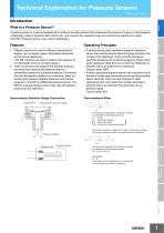
Technical Explanation for Pressure Sensors CSM_Pressure_TG_E_2_2 Introduction Sensors What Is a Pressure Sensor? A pressure sensor is a device equipped with a pressure-sensitive element that measures the pressure of a gas or a liquid against a diaphragm made of stainless steel, silicon, etc., and converts the measured value into an electrical signal as an output. (The E8 Pressure Sensors use a silicon diaphragm.) Operating Principles Semiconductor distortion gauge Control Components Protective film Semiconductor Distortion Gauge Construction • A semiconductor piezo-resistance dispersion pressure sensor has a semiconductor distortion gauge formed on the surface of the diaphragm, and it converts changes in electrical resistance into an electrical signal by means of the piezo-resistance effect that occurs when the diaphragm is distorted due to an external force (pressure). Typical model: E8F2 • A static capacitance pressure sensor has a capacitor that is formed by a static glass electrode and an opposing movable silicon electrode, and it converts changes in static capacitance that occur when the movable electrode is distorted due to an external force (pressure) into an electrical signal. Typical model: E8Y Safety Components 1. Different sensors are used for different measurement targets, such as liquids, gases, flammable substances, and corrosive substances. (The E8 Sensors are used to measure the pressure of non-flammable and non-corrosive gases.) 2. There are sensors that measure the absolute pressure and those that measure the pressure relative to atmospheric pressure or a specified pressure. For sensors that use atmospheric pressure as a reference, there are sensors that measure negative pressures and positive pressures. (The E8Y is a differential pressure sensor. The E8F2 is a gauge pressure sensor that uses atmospheric pressure as the reference.) Automation Systems S The electrical resistance of the above conductor is expressed by the following formula: R = ρ x L/S. ρ: Electrical resistivity L: Conductor length S: Conductor cross-sectional area Motion / Drives When this conductor is pulled to the right or left as shown below, the length increases and the cross-sectional area decreases. Pressure is applied. L+1 Gauge foil pattern Energy Conservation Support / Environment Measure Equipment The electrical resistance of the above conductor is expressed by the following formula: R' = ρ x (L+1)/(S−s). Accordingly, R' > R. This shows how the application of a mechanical force changes the electrical resistance. Power Supplies / In Addition Othe
Open the catalog to page 1
Technical Explanation for Pressure Sensors Reference pressure Gauge Pressure The amount of pressure is expressed in terms of atmospheric pressure. It is referred to as "positive pressure" when it is greater than one atmosphere, and "negative pressure" when it is less than one atmosphere. Absolute Pressure This is the amount of pressure expressed in relation to an absolute vacuum. Pressure Difference (Relative Pressure) This is the amount of pressure compared to any particular pressure (the reference pressure). Negative Positive pressure ! pressure Absolute Atmospheric vacuum pressure Atmospheric...
Open the catalog to page 2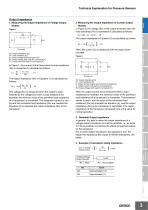
Output Impedance 1. Measuring the Output Impedance of Voltage Output Models Figure 1 The output impedance in Equation (3) is calculated as follows: Ro = Rx (■ - ) (4) The output impedance (Ro) in Equation (1) is calculated as follows: Here, the current (Io) is measured with the output short-circuited. Figure 2 The voltage (Eo) is measured when the output is open, followed by the voltage (Ex) when a load resistance (for example, the minimum value of the permitted load resistance of a transducer) is connected. The measured values Eo and Ex and the connected load resistance (Rx) are inserted into...
Open the catalog to page 3All OMRON catalogs and technical brochures
Archived catalogs
 D4F
D4F8 Pages
 D4GS-N
11 Pages
 E4E2
E4E25 Pages
 Fiber SensorBest Selection Catalog
104 Pages
 Fiber Unit E32-LT/LD
4 Pages
 G9SE Series
20 Pages
 R87F / R87T AC Axial Fans
28 Pages
 Displacement Sensors
4 Pages
 Photomicro Sensors
7 Pages
 Switching Power Supplies
16 Pages
 DeviceNet Safety System
30 Pages
 Programmable Terminals NS Series
57 Pages
 Data Logger ZR-RX Series
12 Pages
 Switch Mode Power Supply S8VK-G
22 Pages
 E3FA PHOTOELECTRIC SENSORS
24 Pages
 Safety Controller G9SP
28 Pages
 Round Water-resistant Connectors
31 Pages
 NT series
18 Pages
 Air Particle Sensor ZN-PD-S
2 Pages
 Portable Multi-logger ZR-RX70
12 Pages
 Fiber Sensor Best Selection Catalog
100 Pages
 Code Reader/OCR
24 Pages
 F3SJ Series Safety Light Curtain
108 Pages
 CompoNet
28 Pages
 Vision System FH series
54 Pages
 E9NC-T
2 Pages
 ZW Series
24 Pages
 ZS Series
32 Pages
 ZG2
ZG216 Pages
 FZ4 Series
42 Pages
 VC-DL100
6 Pages
 MS4800
40 Pages
 CP1E
CP1E12 Pages
 CP1
CP112 Pages
 E5AC-T
8 Pages
 H8PS Cam Positioner
32 Pages
 OS32C Safety Laser Scanner
24 Pages
 FQ Vision Sensor
17 Pages
 ZN-PD Air Particle Sensor
16 Pages
 S8EX Switch Mode Power Supply
24 Pages
 CP1L CP series CP1L CPU Unit
36 Pages
 E2EF
E2EF8 Pages
 FQ2 Smart camera
24 Pages
 VT-X700
6 Pages
 Sysmac Catalog
410 Pages
 G5 Series
59 Pages
 E3T Series
6 Pages
 E3T Data Sheet
26 Pages
 E3ZM-C
14 Pages
 E3S-CL
9 Pages
 E3S-A
E3S-A21 Pages
 E3S-R
E3S-R11 Pages
 E3S-GS3E4
3 Pages
 D5A
D5A8 Pages
 D5F
D5F5 Pages
 SC
SC5 Pages
 VB
VB5 Pages
 NL
NL8 Pages
 E6A2-C
5 Pages
 E6B2-C
5 Pages
 E6D-C
E6D-C5 Pages
 E6F-C
E6F-C5 Pages
 E6H-C
E6H-C5 Pages
 E4C-UDA
5 Pages
 E4A-3K
9 Pages
 E4B
E4B12 Pages
 G7J
G7J10 Pages
 G7Z
G7Z9 Pages
 G4Q
G4Q6 Pages
 MMK
MMK14 Pages
 MM
MM17 Pages
 MK-S(X)
12 Pages
 MK-S
MK-S9 Pages
 G2AK
G2AK7 Pages
 G2A-434
7 Pages
 G2A
G2A9 Pages
 G7T
G7T7 Pages
![G2R-[]-S](https://img.directindustry.com/pdf/repository_di/15954/g2r-s-616653_1mg.jpg) G2R-[]-S
G2R-[]-S11 Pages
 LY
LY14 Pages
 NE0A-SCPU01
6 Pages
![NE1A-SCPU0[]-EIP](https://img.directindustry.com/pdf/repository_di/15954/ne1a-scpu0-eip-616667_1mg.jpg) NE1A-SCPU0[]-EIP
NE1A-SCPU0[]-EIP8 Pages
 NE1A-SCPU Series
8 Pages
 61F-GPN-BT / -BC
5 Pages
 E3NC-L/-S
16 Pages
 MY
MY35 Pages
 V680S Series
68 Pages
 V680 series
68 Pages
 TL-L
TL-L5 Pages
 GLS
GLS3 Pages
 F92A
F92A4 Pages
 XS2
XS229 Pages
 XS5
XS525 Pages
 APR-S
APR-S6 Pages
 SAO
SAO13 Pages
 SE
SE15 Pages
 K2CM
K2CM16 Pages
 K8AK-TH
12 Pages
 K8AK-LS
12 Pages
 K8AK-TS/PT
12 Pages
 K8DS-PZ
12 Pages
 K8DS-PU
12 Pages
 K8AK-PW
12 Pages
 K8DS-PA
12 Pages
 K8AK-PA
12 Pages
 K8DS-PM
12 Pages
 K8AK-PM
16 Pages
 K8DS-PH
12 Pages
 K8AK-PH
12 Pages
 K8AK-VW
12 Pages
 K8AK-VS
12 Pages
 K8AK-AW
16 Pages
 K8AK-AS
12 Pages
 G9SA-300-SC
9 Pages
 WS02-CFSC1-E
3 Pages
 DST1 Series
5 Pages
 G9SA
G9SA16 Pages
 G9SB
G9SB10 Pages
 G9SX-LM
28 Pages
 G9SX/G9SX-GS
49 Pages
 G9SX-SM/LM
9 Pages
 G9SX-SM
24 Pages
 G9SP
G9SP28 Pages
 NX-SL/SI/SO
20 Pages
 REGULATION SOLUTIONS
24 Pages
 Sensor Accessories
38 Pages
 SMART REMOTE I/O
12 Pages
 SAFETY APPLICATION HANDBOOK
55 Pages
 Vision Systems
20 Pages


