SE
1 /15Pages

SE
1 /15Pages
Catalog excerpts

Solid-state Relay Provides Three Operating Functions in a Compact Package • Prevents burnouts in 3-phase induction motors due to overcurrent, open-phase, or reverse-phase. • LEDs indicate operation of the selected operating function. • Wide setting ranges: current: 1 to 160 A; operating time: 1 to 40 s. • Protects the motor from reversing without starting it. The SE cannot be used with circuits with distorted waveforms, inverter circuits, or capacitor loads. ■ Model Number Legend 6. Reset method None: Manual reset A: Automatic reset 7. Operating value None: 115% of the current SV E: 100% of the current SV 8. Product history N: New version 1. Basic model name SE: Motor Protective Relay 2. Protective functions K: Three possible operating functions: overcurrent, open- phase, or reverse-phase protection 3. Operating time characteristics for overload element Q: Instantaneous type: Fixed time at starting and instanta neous during operation None: Inverse type: Inverse operation both at starting and during operation None: Flush mount type Note: A 3-phase transformer (sold separately) must be used to operate Plug-in Relays at 380, 400, 415, or 440 VAC. Drop the primary voltage (380 to 440 VAC) to a 200-VAC secondary voltage before applying it to the SE-KP2EN or SE-KQP2EN. Overcurrent operating value: 100% of the current SV. Note: With start-up lock: fixed time-limit on start-up, instantaneous thereafter. Plug-in type requires a socket (8PFA1) which is sold separately. Refer to page 9 for the mounting conditions.
Open the catalog to page 1
Overcurrent operating value: 115% of current SV.
Open the catalog to page 2
Engineering DataOperating Characteristics Overcurrent Operating Time Characteristics Overcurrent Operating Time Characteristics (lnverse Type) (Instantaneous Type - Start-up Lock) Time Changeover Switch: x1
Open the catalog to page 4
Operation■ SettingsMotor Relay Switch Settings LED Indicators The LEDs indicate which function is in operation. OPEN refers to open-phase, OC refers to overcurrent, and RVS refers to reverse-phase. Manual Reset The reset button will pop out about 4 mm when the relay has been tripped. After the relay has operated, reset by pressing this button. Disconnect the power supply before resetting for reverse-phase operation. Function Setting DIP SW The three ON/OFF switches enable or disable the three functions. The functions can be enabled in any combination. With the open-phase function, the H/L switch...
Open the catalog to page 5
SE Selecting the Current Converter The current requirements of the motor determine the current range of the Motor Protective Relay, and whether the SET-3A or SET-3B Current Converter should be used, as shown in the following table. Motor specifications kW Motor Protective Relay A Current Converter Current range Note: 1. Connect to the secondary of a commercial current transformer for motors exceeding 37 kW. 2. Connect a commercial current transformer when using high-voltage motors or low-voltage high-capacity motors. Installation ■ Internal Circuit Inverse Type OC: overcurrent LED OPEN: open-phase...
Open the catalog to page 6
■ Connections External Connections Manual Operation Low-voltage Circuit R Automatic Operation Low-voltage Circuit R Alarm buzzer Electromagnetic contactor Automatic contact Electromagnetic contactor High-tension Motor No-voltage Tripping Circuit Manual Operation Low-voltage Circuit Δ Start) Phase advancing capacitor SET-3 Current Converter SE series Motor Protective Relay SE series Motor Protective Relay (C+) (C−) (U) (V) Phase advancing capacitor Alarm buzzer Alarm buzzer Alarm buzzer No-voltage tripping coil Oil circuit breaker Magnet contactor 6 6 SE series Motor Protective Relay Phase advancing...
Open the catalog to page 7
SE Manual Operation Low-voltage Circuit (When using a SE-K@P2@N in a 400/440 VAC Circuit) R Automatic Operation Low-voltage Circuit (High-capacity Motor) Magnet contactor Stop Alarm buzzer Alarm buzzer Automatic contact SE series Motor Protective Relay Magnet contactor Phase advancing capacitor Current transformer SE-K@P2@N Motor Protective Relay Phase advancing capacitor Manual Operation Low-voltage Circuit (Using the Overcurrent and Open-phase Functions) T Control power supply Stop Stop Start Alarm buzzer Alarm buzzer Magnet contactor Magnet contactor SE series Motor Protective Relay SE series...
Open the catalog to page 8
Dimensions Note: All units are in millimeters unless otherwise indicated. Plug-in Socket Terminal SE-KP@N, SE-KQP@N The Height of DIN Rail Mounting Flush Mount Type SE-K@N, SE-KQ@N Panel Cutout Three, 20-dia. through holes Mounting Holes Four, 6-dia. mounting holes or four, M5 mounting screw holes 33.5 112 Note: The SE-PT400 can be used for all 200/220/240-VAC SE Relays. Primary voltage: 380 to 480 VAC Secondary voltage: 190 to 240 VAC Note: This Adapter is used to replace existing flush mount models with new models. Plate material: Steel plate (thickness: 2.0 mm) Color: Black (Munsell N1.5)
Open the catalog to page 9
■ Testing Method With the circuit shown below, the characteristics listed in the following table can be tested. Determine the number of conductor runs through the holes of the current transformer in accordance with the operating current range of the Motor Protective Relay and by referring to the table in the section Selecting the Current Converter. 3^SD: 3-phase voltage regulator (5 to 15 A) A: AC ammeter SWi: knife switch (three-phase) SW2: toggle switch
Open the catalog to page 10
■ Checking Operation Checklist After Connection and Before Starting Motor Check the Current Converter for the proper number of conductor runs through holes and the proper direction. Relay operates instantaneously Test Operation Corrective action Apply control power supply to the relay Change the phasesequence of 3-phase voltage properly. Check the Current Converter and Motor Protective Relay for connection with proper polarity. Press the test button (for longer than the set time). Check the phase-sequence of 3-phase voltage (for 3E relays). Does the relay operate? Check for: 1. Loose terminal...
Open the catalog to page 11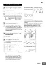
Questions and Answers When using the SE as a 2E (overload and open-phase) relay, can the control power supply voltage be supplied separately from the motor circuit? Complete open-phase loss Why is the control power supply 100/110 V? The main reason the SE uses a 100/110-V control power supply is because 100/110 V is applicable to high-voltage motor protection. With a high-voltage motor, the voltage is first reduced with a potential transformer, and the secondary side is connected to the SE. When using the SE as a 2E (overload and open-phase) relay, a normal 100-V power supply can be used without...
Open the catalog to page 12All OMRON catalogs and technical brochures
 D4F
D4F8 Pages
 D4GS-N
11 Pages
 E4E2
E4E25 Pages
 Fiber SensorBest Selection Catalog
104 Pages
 Fiber Unit E32-LT/LD
4 Pages
 G9SE Series
20 Pages
 NX-SL/SI/SO
20 Pages
 G9SP
G9SP28 Pages
 G9SX-SM
24 Pages
 G9SX-SM/LM
9 Pages
 G9SX/G9SX-GS
49 Pages
 G9SX-LM
28 Pages
 G9SB
G9SB10 Pages
 G9SA
G9SA16 Pages
 DST1 Series
5 Pages
 WS02-CFSC1-E
3 Pages
 G9SA-300-SC
9 Pages
 K8AK-AS
12 Pages
 K8AK-AW
16 Pages
 K8AK-VS
12 Pages
 K8AK-VW
12 Pages
 K8AK-PH
12 Pages
 K8DS-PH
12 Pages
 K8AK-PM
16 Pages
 K8DS-PM
12 Pages
 K8AK-PA
12 Pages
 K8DS-PA
12 Pages
 K8AK-PW
12 Pages
 K8DS-PU
12 Pages
 K8DS-PZ
12 Pages
 K8AK-TS/PT
12 Pages
 K8AK-LS
12 Pages
 K8AK-TH
12 Pages
 K2CM
K2CM16 Pages
 SAO
SAO13 Pages
 APR-S
APR-S6 Pages
 XS5
XS525 Pages
 XS2
XS229 Pages
 F92A
F92A4 Pages
 GLS
GLS3 Pages
 TL-L
TL-L5 Pages
 V680 series
68 Pages
 V680S Series
68 Pages
 MY
MY35 Pages
 E3NC-L/-S
16 Pages
 61F-GPN-BT / -BC
5 Pages
 NE1A-SCPU Series
8 Pages
![NE1A-SCPU0[]-EIP](https://img.directindustry.com/pdf/repository_di/15954/ne1a-scpu0-eip-616667_1mg.jpg) NE1A-SCPU0[]-EIP
NE1A-SCPU0[]-EIP8 Pages
 NE0A-SCPU01
6 Pages
 LY
LY14 Pages
![G2R-[]-S](https://img.directindustry.com/pdf/repository_di/15954/g2r-s-616653_1mg.jpg) G2R-[]-S
G2R-[]-S11 Pages
 G7T
G7T7 Pages
 G2A
G2A9 Pages
 G2A-434
7 Pages
 G2AK
G2AK7 Pages
 MK-S
MK-S9 Pages
 MK-S(X)
12 Pages
 MM
MM17 Pages
 MMK
MMK14 Pages
 G4Q
G4Q6 Pages
 G7Z
G7Z9 Pages
 G7J
G7J10 Pages
 E4B
E4B12 Pages
 E4A-3K
9 Pages
 E4C-UDA
5 Pages
 E6H-C
E6H-C5 Pages
 E6F-C
E6F-C5 Pages
 E6D-C
E6D-C5 Pages
 E6B2-C
5 Pages
 E6A2-C
5 Pages
 NL
NL8 Pages
 VB
VB5 Pages
 SC
SC5 Pages
 D5F
D5F5 Pages
 D5A
D5A8 Pages
 E3S-GS3E4
3 Pages
 E3S-R
E3S-R11 Pages
 E3S-A
E3S-A21 Pages
 E3S-CL
9 Pages
 E3ZM-C
14 Pages
 E3T Data Sheet
26 Pages
 E3T Series
6 Pages
 G5 Series
59 Pages
 Sysmac Catalog
410 Pages
 VT-X700
6 Pages
 E5AC-T
8 Pages
 CP1
CP112 Pages
 CP1E
CP1E12 Pages
 MS4800
40 Pages
 VC-DL100
6 Pages
 FZ4 Series
42 Pages
 ZG2
ZG216 Pages
 ZS Series
32 Pages
 ZW Series
24 Pages
 E9NC-T
2 Pages
 Vision System FH series
54 Pages
 CompoNet
28 Pages
 F3SJ Series Safety Light Curtain
108 Pages
 Code Reader/OCR
24 Pages
 Fiber Sensor Best Selection Catalog
100 Pages
 Portable Multi-logger ZR-RX70
12 Pages
 Air Particle Sensor ZN-PD-S
2 Pages
 NT series
18 Pages
 Round Water-resistant Connectors
31 Pages
 Safety Controller G9SP
28 Pages
 E3FA PHOTOELECTRIC SENSORS
24 Pages
 Switch Mode Power Supply S8VK-G
22 Pages
 Data Logger ZR-RX Series
12 Pages
 Programmable Terminals NS Series
57 Pages
 DeviceNet Safety System
30 Pages
 Switching Power Supplies
16 Pages
 Photomicro Sensors
7 Pages
 Displacement Sensors
4 Pages
 R87F / R87T AC Axial Fans
28 Pages
 H8PS Cam Positioner
32 Pages
 OS32C Safety Laser Scanner
24 Pages
 FQ Vision Sensor
17 Pages
 ZN-PD Air Particle Sensor
16 Pages
 S8EX Switch Mode Power Supply
24 Pages
 CP1L CP series CP1L CPU Unit
36 Pages
 E2EF
E2EF8 Pages
 FQ2 Smart camera
24 Pages


Archived catalogs
 REGULATION SOLUTIONS
24 Pages
 Sensor Accessories
38 Pages
 SMART REMOTE I/O
12 Pages
 SAFETY APPLICATION HANDBOOK
55 Pages
 Vision Systems
20 Pages
- SARRALLE industrial robot
- Digital I/O
- Single-pole switch
- IO module
- Propeller fan
- Push-button switch
- SARRALLE air circulation fan
- Digital temperature control
- Terminal box
- SARRALLE industrial fan
- Analog I/O
- Switching relay
- SARRALLE digital indicator
- Digital IO module
- SARRALLE handling robot
- SARRALLE 3D software
- AC fan
- SARRALLE interface software
- SARRALLE panel-mount indicator
- SARRALLE simulation software