SAO
1 /13Pages

SAO
1 /13Pages
Catalog excerpts

Solid-state, Plug-in Current Sensor • Applicable to motor overcurrent protection and 3-phase AC current detection. • Inverse-type, start-up lock type, and instantaneous type overcurrent sensors available. • Instantaneous type under current sensor available. • Plug-in design simplifies installation, removal, and wiring. • DIN sized (48 mm x 96 mm) The SAO cannot be used in circuits with waveform distortion, inverter circuits, or with capacitor loads. Model Number Structure ■ Model Number Legend SAO-rnm 1 2 3 4 5 1. Basic model name 4. SAO: Current Sensor 2. Operating time characteristics R: Inverse type: inverse time both at starting and during oper ation Q: Instantaneous type with start-up lock 3. Detection function U: Undercurrent detection None: Overcurrent detection Product history N: New version
Open the catalog to page 1
■ Characteristics (continued) Insulation resistance Time Changeover Setting: 1 SAO-Q Time Changeover Setting: 4 °.8 Current (% of operating current) Current (% of operating current)
Open the catalog to page 3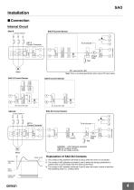
Installation ■ Connection Internal Circuit SAO-R SAO-R Current Sensor Control voltage Power supply circuit Overcurrent detecting circuit Rectifying circuit Note: There is no polarity specification when using a DC power supply. SAO-Q Current Sensor SAO-SU Current Sensor Power supply circuit Overcurrent detecting circuit Rectifying circuit Control voltage Overcurrent detecting circuit Start-up mode time SV circuit Start-up detecting circuit Overcurrent detecting circuit SAO-S Current Sensor Test NORMAL: LED indicates operation. (ON for a steady current, OFF for an under current.) M Motor (A) Reset...
Open the catalog to page 4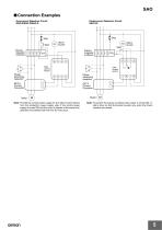
SAO ■ Connection Examples Overcurrent Detection Circuit SAO-R/SAO-Q/SAO-S R Undercurrent Detection Circuit SAO-SU R Stop Start Alarm buzzer Alarm buzzer Start Electromagnetic contactor Phase advancing capacitor Phase advancing capacitor SET-3 Current Converter Note: Provide the control power supply for the SAO Current Sensor from the contactor’s power supply side. If the control power supply is turned ON and the motor is started at the same time, operation inconsistent with the time SV may occur. Note: To prevent the buzzer sounding when power is turned ON, install a timer so that the buzzer...
Open the catalog to page 5
Operation ■ SettingsCurrent Sensor Switch Settings Current Scale Multiplying Factor Decal Determine the current scale multiplying factor corresponding to the current SV range obtained from Table 1 and paste the current scale multiplying decal to the current sensor. For example, when the current setting range is 2 to 5 A, the decal no. is 0.5. LED Indicator The LED indicates that an overcurrent has occurred and the relay is operating. Setting Operating Time Set the time setting knob to the required time. The operating time is equal to the time scale value times the setting on the time changeover...
Open the catalog to page 6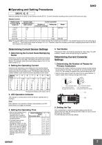
■ Operating and Setting Procedures SAO-R, -Q, -S Make the settings for the SAO Current Sensor and the SET-3D Current Converter according to the current of the load to be used. Steady Current The figures are steady current values. (Unit: A) Determining Current Sensor Settings 1. Determining the Current Scale Multiplying Factor Determine a current scale multiplying factor that matches the steady current obtained from the table, and attach that decal to the Current Sensor. For example, when the current setting range is 2 to 5 A, the label number is 0.5. 2. Setting the Operating Current Determine...
Open the catalog to page 7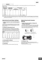
SAO-SU Make the settings for the SAO-SU Current Sensor and the SET-3D Current Converter according to the current of the load to be used. Steady Current Determining Current Sensor Settings 1. Determining the Current Scale Multiplying Factor Determine a current scale multiplying factor that matches the steady current obtained from the table, and attach that decal to the Current Sensor. For example, when the current setting range is 2 to 5 A, the label number is 0.5. 2. Setting the Operating Current Determine the operating current setting from the required steady current and the label number (i.e.,...
Open the catalog to page 8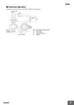
SAO ■ Checking Operation The following circuit can be used to check SAO-@ and SET-3@ characteristics. 200 VAC, 3-phase, 50/60 Hz R S T Control voltage Three-phase voltage regulator AC ammeter Cycle counter Auxiliary relay (15 A) Resistor
Open the catalog to page 9
Dimensions Note: All units are in millimeters unless otherwise indicated. SAO-R/SAO-Q The Height of DIN Rail Mounting Current Converter SET-3A, SET-3B Mounting Holes Four, 6-dia. mounting holes or four, M5 mounting screw holes
Open the catalog to page 10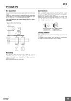
Use a commercial frequency power supply only for the control power supply. Make sure that the polarity is correct when connecting the Current Converter and Current Sensor. It is not necessary to consider polarity when using a DC control power supply. The SET-3@ Current Converter is designed for use with a single SAO Current Sensor; do not connect two units to a single SET-3@ as in figure 1 below (even if a diode is included in the circuit). If the current transformer has sufficient capacity, the circuit in figure 2 is acceptable. Determine the necessary number of conductor runs from the table...
Open the catalog to page 11
What is the procedure for using the SAO with a single phase? The following describes the single-phase operating procedure for the SAO. Models for single-phase circuits, however, are also available. Refer to SAO-@S. Connection Procedure Run the primary wires through any two of the three holes on the SET3 the number of times specified for the SET-3@. Can two SAO Current Sensors be used connected to one SET-3@? If not, can a diode or other device be inserted? It is not possible to connect two SAO Current Sensors to one SET-3@. The SET-3 output is designed so that the output voltage will match when...
Open the catalog to page 12
Terms and Conditions Agreement Read and understand this catalog. Please read and understand this catalog before purchasing the products. Please consult your OMRON representative if you have any questions or comments. Warranties. (a) Exclusive Warranty. Omron’s exclusive warranty is that the Products will be free from defects in materials and workmanship for a period of twelve months from the date of sale by Omron (or such other period expressed in writing by Omron). Omron disclaims all other warranties, express or implied. (b) Limitations. OMRON MAKES NO WARRANTY OR REPRESENTATION, EXPRESS OR...
Open the catalog to page 13All OMRON catalogs and technical brochures
 D4F
D4F8 Pages
 D4GS-N
11 Pages
 E4E2
E4E25 Pages
 Fiber SensorBest Selection Catalog
104 Pages
 Fiber Unit E32-LT/LD
4 Pages
 G9SE Series
20 Pages
 NX-SL/SI/SO
20 Pages
 G9SP
G9SP28 Pages
 G9SX-SM
24 Pages
 G9SX-SM/LM
9 Pages
 G9SX/G9SX-GS
49 Pages
 G9SX-LM
28 Pages
 G9SB
G9SB10 Pages
 G9SA
G9SA16 Pages
 DST1 Series
5 Pages
 WS02-CFSC1-E
3 Pages
 G9SA-300-SC
9 Pages
 K8AK-AS
12 Pages
 K8AK-AW
16 Pages
 K8AK-VS
12 Pages
 K8AK-VW
12 Pages
 K8AK-PH
12 Pages
 K8DS-PH
12 Pages
 K8AK-PM
16 Pages
 K8DS-PM
12 Pages
 K8AK-PA
12 Pages
 K8DS-PA
12 Pages
 K8AK-PW
12 Pages
 K8DS-PU
12 Pages
 K8DS-PZ
12 Pages
 K8AK-TS/PT
12 Pages
 K8AK-LS
12 Pages
 K8AK-TH
12 Pages
 K2CM
K2CM16 Pages
 SE
SE15 Pages
 APR-S
APR-S6 Pages
 XS5
XS525 Pages
 XS2
XS229 Pages
 F92A
F92A4 Pages
 GLS
GLS3 Pages
 TL-L
TL-L5 Pages
 V680 series
68 Pages
 V680S Series
68 Pages
 MY
MY35 Pages
 E3NC-L/-S
16 Pages
 61F-GPN-BT / -BC
5 Pages
 NE1A-SCPU Series
8 Pages
![NE1A-SCPU0[]-EIP](https://img.directindustry.com/pdf/repository_di/15954/ne1a-scpu0-eip-616667_1mg.jpg) NE1A-SCPU0[]-EIP
NE1A-SCPU0[]-EIP8 Pages
 NE0A-SCPU01
6 Pages
 LY
LY14 Pages
![G2R-[]-S](https://img.directindustry.com/pdf/repository_di/15954/g2r-s-616653_1mg.jpg) G2R-[]-S
G2R-[]-S11 Pages
 G7T
G7T7 Pages
 G2A
G2A9 Pages
 G2A-434
7 Pages
 G2AK
G2AK7 Pages
 MK-S
MK-S9 Pages
 MK-S(X)
12 Pages
 MM
MM17 Pages
 MMK
MMK14 Pages
 G4Q
G4Q6 Pages
 G7Z
G7Z9 Pages
 G7J
G7J10 Pages
 E4B
E4B12 Pages
 E4A-3K
9 Pages
 E4C-UDA
5 Pages
 E6H-C
E6H-C5 Pages
 E6F-C
E6F-C5 Pages
 E6D-C
E6D-C5 Pages
 E6B2-C
5 Pages
 E6A2-C
5 Pages
 NL
NL8 Pages
 VB
VB5 Pages
 SC
SC5 Pages
 D5F
D5F5 Pages
 D5A
D5A8 Pages
 E3S-GS3E4
3 Pages
 E3S-R
E3S-R11 Pages
 E3S-A
E3S-A21 Pages
 E3S-CL
9 Pages
 E3ZM-C
14 Pages
 E3T Data Sheet
26 Pages
 E3T Series
6 Pages
 G5 Series
59 Pages
 Sysmac Catalog
410 Pages
 VT-X700
6 Pages
 E5AC-T
8 Pages
 CP1
CP112 Pages
 CP1E
CP1E12 Pages
 MS4800
40 Pages
 VC-DL100
6 Pages
 FZ4 Series
42 Pages
 ZG2
ZG216 Pages
 ZS Series
32 Pages
 ZW Series
24 Pages
 E9NC-T
2 Pages
 Vision System FH series
54 Pages
 CompoNet
28 Pages
 F3SJ Series Safety Light Curtain
108 Pages
 Code Reader/OCR
24 Pages
 Fiber Sensor Best Selection Catalog
100 Pages
 Portable Multi-logger ZR-RX70
12 Pages
 Air Particle Sensor ZN-PD-S
2 Pages
 NT series
18 Pages
 Round Water-resistant Connectors
31 Pages
 Safety Controller G9SP
28 Pages
 E3FA PHOTOELECTRIC SENSORS
24 Pages
 Switch Mode Power Supply S8VK-G
22 Pages
 Data Logger ZR-RX Series
12 Pages
 Programmable Terminals NS Series
57 Pages
 DeviceNet Safety System
30 Pages
 Switching Power Supplies
16 Pages
 Photomicro Sensors
7 Pages
 Displacement Sensors
4 Pages
 R87F / R87T AC Axial Fans
28 Pages
 H8PS Cam Positioner
32 Pages
 OS32C Safety Laser Scanner
24 Pages
 FQ Vision Sensor
17 Pages
 ZN-PD Air Particle Sensor
16 Pages
 S8EX Switch Mode Power Supply
24 Pages
 CP1L CP series CP1L CPU Unit
36 Pages
 E2EF
E2EF8 Pages
 FQ2 Smart camera
24 Pages


Archived catalogs
 REGULATION SOLUTIONS
24 Pages
 Sensor Accessories
38 Pages
 SMART REMOTE I/O
12 Pages
 SAFETY APPLICATION HANDBOOK
55 Pages
 Vision Systems
20 Pages
- SARRALLE industrial robot
- Digital I/O
- Single-pole switch
- IO module
- Propeller fan
- Push-button switch
- SARRALLE air circulation fan
- Digital temperature control
- SARRALLE industrial fan
- Terminal box
- Switching relay
- Analog I/O
- SARRALLE digital indicator
- Digital IO module
- SARRALLE handling robot
- SARRALLE 3D software
- AC fan
- SARRALLE interface software
- SARRALLE panel-mount indicator
- SARRALLE simulation software