Photoelectric Sensor with Separate Digital Amplifier (Laser-type)E3C-LDA
1 /17Pages

Photoelectric Sensor with Separate Digital Amplifier (Laser-type)E3C-LDA
1 /17Pages
Catalog excerpts

Photoelectric Sensor with Separate Digital Amplifier (Laser-type) Variable Laser Beam for Spot, Line, or Area Detection • Long-distance detection (diffuse reflective: 1 m, retro-reflective: 7 m). • Beam shape selectable from spot, line, and area types to match various applications. • Adjustable spot diameter. • Adjustable optical axis. • The E3DC-LDA0, which supports the EtherCAT Sensor Communications Unit and the CompoNet Sensor Communications Unit, is also included in product lineup. Refer to Safety Precautions on page 9. For the most recent information on models that have been certified for safety standards, refer to your OMRON website. Features Diffuse Reflective Model ■ All three beam types provide ample long-distance detection of 1,000 mm. Three beam types means a wider variety of applications. ■Spot, Line, and Area Types At 1,000 mm: Minimum spot diameter of 950 µm Suitable for various applications without any additional costs. ■Variable Focal Point Mechanism Mount Beam Units to a Spot Type Sensor to convert to Line or Area Type. Optical axis alignment range: Approximately ±2° Spot Type Spot diameter can be adjusted to enable ultra-high-precision positioning. ■Optical Axis Adjustment Mechanism The sensor detection point can be easily changed. 8 mm - 0.2 mm - 3.5 mm (VR minimum) (VR median) (VR maximum) (VR minimum) (VR median) (VR maximum) Line Type Area Type Coaxial Retroreflective Model ■ Easy Sensor Installation and Sensing Characteristics Equivalent to Through-beam Sensors. ■Variable Focal Point Mechanism Optical axis alignment range: Approximately ±1 to1.5° ■Optical Axis Adjustment Mechanism At 1 m: Minimum spot diameter of 0.8 mm ■Spot, Line, and Area Types Spot Type ■Coaxial Optical System The coaxial optical system and laser beam allow high-precision detection. The built-in MSR Function inhibits the effect of reflecte
Open the catalog to page 1
Ordering Information Sensor Heads (Dimensions ^ page 12, 13)
Open the catalog to page 2
E3C-LDA Mobile Console (Dimensions ➜ E3X-DA-S/MDA) Appearance Mobile Console with Head, E3X-MC11-SV2 Cable, and AC adapter (model number of set) provided as accessories Mobile Console Note: Use the E3X-MC11-S Mobile Console for the E3X-LDA Series Amplifier Units. The E3X-MC11-SV2 is an upgraded version of the E3X-MC11-S that is fully interchangeable with the older model. Refer to E3X-DA-S/MDA for details. Beam Unit (for E3C-LD11/LR11) A Beam Unit is not provided with the Sensor and must be ordered separately as required. Applicable Sensor Head Beam shape Reflectors (Required when using retro-reflective...
Open the catalog to page 3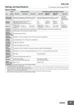
For dimensions, refer to pages 12 to 16. Sensor Heads Type Item Coaxial Retro-reflective (with M.S.R. function) Light source (wavelength) Red semiconductor laser diode (650 nm), 3 mW max. Red semiconductor laser diode (650 nm), 3 mW max. (JIS Class 2, IEC/EN Class 2, and FDA Class 2) (JIS Class 2, IEC/EN Class 2, and FDA Class 2) 1 mW max. (JIS Class 1, IEC/EN Class 1, and FDA Class 2) Sensing distance High-resolution mode: 30 to 1,000 mm Standard mode: 30 to 700 mm Super-high-speed mode: 30 to 250 mm *1 Variable focal point mechanism (focus adjustment) *4, optical axis adjustment mechanism (axis...
Open the catalog to page 4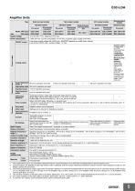
E3C-LDA Amplifier Units Type External-input models Standard models Standard models Wire-saving connector Wire-saving connector ATC-output models Model for Sensor Communications Unit E3C-LDA0 *1 Analog-output models Standard models Twin-output models Standard models Wire-saving connector Supply voltage Power consumption 1,080 mW max. (current consumption: 45 mA max. at power supply voltage of 24 VDC) Response time Control output ON/OFF output Load power supply voltage: 26.4 VDC max.; NPN/PNP (depends on model) open collector Load current: 50 mA max.; residual voltage: 1 V max. Analog output Control...
Open the catalog to page 5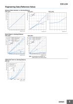
Engineering Data (Reference Value) Minimum Beam Diameter vs. Sensing Distance E3C-LD11 E3C-LR11 Y direction 5 FOCUS control turned all the way to right FOCUS control turned to center FOCUS control turned all the way to left X direction Y direction X direction Y direction X direction Y direction Beam Shape vs. Sensing Distance E3C-LD21 X direction Y direction X direction Y direction FOCUS control turned all the way to right FOCUS control turned all the way to left Note: The dashed lines indicate nonvisible regions of the beam shape. Differential Travel vs. Sensing Distance E3C-LD 50 45 40 Super-high-speed...
Open the catalog to page 6
I/O Circuit Diagrams NPN Output Model Operation mode Timing charts Mode selector switch Output circuit ch1/ Incident light ch2 No incident light Operation Indicator (orange) Output transistor ON OFF Operate Load (e.g., relay) Reset (Between brown and black leads) Operation indicator (orange) ch1 Incident light No incident light Operation ON Indicator OFF (orange) ON Output transistor OFF Operate Load (e.g., relay) Reset (Between brown and black leads) ON OFF Operate Load (e.g., relay) Reset (Between brown and black leads) Brown Black Photoelectric Sensor Main Circuit ch1/ Incident light ch2 No...
Open the catalog to page 7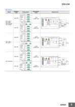
E3C-LDA PNP Output Operation mode Timing charts Mode selector switch ch1/ Incident light ch2 No incident light Operation ON Indicator OFF (orange) ON Output transistor OFF Operate Load (e.g., relay) Reset (Between blue and black leads) ch1/ Incident light ch2 No incident light Operation ON Indicator OFF (orange) ON OFF Operate Load (e.g., relay) Reset (Between blue and black leads) Output transistor Incident light No incident light Operation ON Indicator OFF (orange) ON Output transistor OFF Load Operate (e.g., relay) Reset (Between blue and black leads) Output circuit Operation indicator (orange)...
Open the catalog to page 8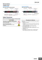
Nomenclature Amplifier Units Twin Output Models (E3C-LDA11/LDA41/LDA6/LDA8/LDA0) External Input Models (E3C-LDA21/LDA51/LDA7/LDA9) Sub-Display (green) Operation Keys Sub-Display (green) Operation Keys Incident level, function, etc. Threshold, function settings, etc. Function setting operations Incident level, function, etc. Threshold, function settings, etc. Function setting operations Channel Selector Operation indicator for channel 1 (orange) Operation indicator for channel 2 (orange) ON when output is ON. OFF when output is OFF. ON when output is ON. OFF when output is OFF. Use to switch between...
Open the catalog to page 9All OMRON catalogs and technical brochures
 D4F
D4F8 Pages
 D4GS-N
11 Pages
 E4E2
E4E25 Pages
 Fiber SensorBest Selection Catalog
104 Pages
 Fiber Unit E32-LT/LD
4 Pages
 G9SE Series
20 Pages
 NX-SL/SI/SO
20 Pages
 G9SP
G9SP28 Pages
 G9SX-SM
24 Pages
 G9SX-SM/LM
9 Pages
 G9SX/G9SX-GS
49 Pages
 G9SX-LM
28 Pages
 G9SB
G9SB10 Pages
 G9SA
G9SA16 Pages
 DST1 Series
5 Pages
 WS02-CFSC1-E
3 Pages
 G9SA-300-SC
9 Pages
 K8AK-AS
12 Pages
 K8AK-AW
16 Pages
 K8AK-VS
12 Pages
 K8AK-VW
12 Pages
 K8AK-PH
12 Pages
 K8DS-PH
12 Pages
 K8AK-PM
16 Pages
 K8DS-PM
12 Pages
 K8AK-PA
12 Pages
 K8DS-PA
12 Pages
 K8AK-PW
12 Pages
 K8DS-PU
12 Pages
 K8DS-PZ
12 Pages
 K8AK-TS/PT
12 Pages
 K8AK-LS
12 Pages
 K8AK-TH
12 Pages
 K2CM
K2CM16 Pages
 SE
SE15 Pages
 SAO
SAO13 Pages
 APR-S
APR-S6 Pages
 XS5
XS525 Pages
 XS2
XS229 Pages
 F92A
F92A4 Pages
 GLS
GLS3 Pages
 TL-L
TL-L5 Pages
 V680 series
68 Pages
 V680S Series
68 Pages
 MY
MY35 Pages
 E3NC-L/-S
16 Pages
 61F-GPN-BT / -BC
5 Pages
 NE1A-SCPU Series
8 Pages
![NE1A-SCPU0[]-EIP](https://img.directindustry.com/pdf/repository_di/15954/ne1a-scpu0-eip-616667_1mg.jpg) NE1A-SCPU0[]-EIP
NE1A-SCPU0[]-EIP8 Pages
 NE0A-SCPU01
6 Pages
 LY
LY14 Pages
![G2R-[]-S](https://img.directindustry.com/pdf/repository_di/15954/g2r-s-616653_1mg.jpg) G2R-[]-S
G2R-[]-S11 Pages
 G7T
G7T7 Pages
 G2A
G2A9 Pages
 G2A-434
7 Pages
 G2AK
G2AK7 Pages
 MK-S
MK-S9 Pages
 MK-S(X)
12 Pages
 MM
MM17 Pages
 MMK
MMK14 Pages
 G4Q
G4Q6 Pages
 G7Z
G7Z9 Pages
 G7J
G7J10 Pages
 E4B
E4B12 Pages
 E4A-3K
9 Pages
 E4C-UDA
5 Pages
 E6H-C
E6H-C5 Pages
 E6F-C
E6F-C5 Pages
 E6D-C
E6D-C5 Pages
 E6B2-C
5 Pages
 E6A2-C
5 Pages
 NL
NL8 Pages
 VB
VB5 Pages
 SC
SC5 Pages
 D5F
D5F5 Pages
 D5A
D5A8 Pages
 E3S-GS3E4
3 Pages
 E3S-R
E3S-R11 Pages
 E3S-A
E3S-A21 Pages
 E3S-CL
9 Pages
 E3ZM-C
14 Pages
 E3T Data Sheet
26 Pages
 E3T Series
6 Pages
 G5 Series
59 Pages
 Sysmac Catalog
410 Pages
 VT-X700
6 Pages
 E5AC-T
8 Pages
 CP1
CP112 Pages
 CP1E
CP1E12 Pages
 MS4800
40 Pages
 VC-DL100
6 Pages
 FZ4 Series
42 Pages
 ZG2
ZG216 Pages
 ZS Series
32 Pages
 ZW Series
24 Pages
 E9NC-T
2 Pages
 Vision System FH series
54 Pages
 CompoNet
28 Pages
 F3SJ Series Safety Light Curtain
108 Pages
 Code Reader/OCR
24 Pages
 Fiber Sensor Best Selection Catalog
100 Pages
 Portable Multi-logger ZR-RX70
12 Pages
 Air Particle Sensor ZN-PD-S
2 Pages
 NT series
18 Pages
 Round Water-resistant Connectors
31 Pages
 Safety Controller G9SP
28 Pages
 E3FA PHOTOELECTRIC SENSORS
24 Pages
 Switch Mode Power Supply S8VK-G
22 Pages
 Data Logger ZR-RX Series
12 Pages
 Programmable Terminals NS Series
57 Pages
 DeviceNet Safety System
30 Pages
 Switching Power Supplies
16 Pages
 Photomicro Sensors
7 Pages
 Displacement Sensors
4 Pages
 R87F / R87T AC Axial Fans
28 Pages
 H8PS Cam Positioner
32 Pages
 OS32C Safety Laser Scanner
24 Pages
 FQ Vision Sensor
17 Pages
 ZN-PD Air Particle Sensor
16 Pages
 S8EX Switch Mode Power Supply
24 Pages
 CP1L CP series CP1L CPU Unit
36 Pages
 E2EF
E2EF8 Pages
 FQ2 Smart camera
24 Pages


Archived catalogs
 REGULATION SOLUTIONS
24 Pages
 Sensor Accessories
38 Pages
 SMART REMOTE I/O
12 Pages
 SAFETY APPLICATION HANDBOOK
55 Pages
 Vision Systems
20 Pages
- SARRALLE industrial robot
- Digital I/O
- Single-pole switch
- IO module
- Propeller fan
- Push-button switch
- SARRALLE air circulation fan
- Digital temperature control
- Terminal box
- SARRALLE industrial fan
- Analog I/O
- Switching relay
- SARRALLE digital indicator
- Digital IO module
- SARRALLE handling robot
- SARRALLE 3D software
- AC fan
- SARRALLE interface software
- SARRALLE panel-mount indicator
- SARRALLE simulation software