OS32C Safety Laser Scanner
1 /24Pages

OS32C Safety Laser Scanner
1 /24Pages
Catalog excerpts

Safety Laser Scanner 0S32C Compliant with Performance Level d/Safety Category 3 Compact, Lightweight and Easy-To-Use Safety Laser Scanner » Saves power consumption greatly. Supports various applications with simple operation. » Easy settings with a PC
Open the catalog to page 1
Features Low profile allows installation in small spaces For collision avoidance of AGVs (Automated Guided Vehicles) For intrusion detection through an entrance ach For presence detection within a machine's hazardous area Safety Zone 3 m Max. Detection Angle 270° Max. Compact size allows: 3 m* safety zone, 270° detection angle. * The minimum object resolution is 50/70 mm. Warning Zones 1&2 10 m Max. World’s Most Compact Level Small Size 104.5 mm Compact and versatile safety laser scanner 104.5mm Lightweight 1.3 kg Lightweight body for easy handling and installation 142.7mm Low Power Consumption...
Open the catalog to page 2
Features Low profile allows installation in small spaces For collision avoidance of AGVs (Automated Guided Vehicles) For intrusion detection through an entrance ach For presence detection within a machine's hazardous area Safety Zone 3 m Max. Detection Angle 270° Max. Compact size allows: 3 m* safety zone, 270° detection angle. * The minimum object resolution is 50/70 mm. Warning Zones 1&2 10 m Max. World’s Most Compact Level Small Size 104.5 mm Compact and versatile safety laser scanner 104.5mm Lightweight 1.3 kg Lightweight body for easy handling and installation 142.7mm Low Power Consumption...
Open the catalog to page 3
Applications New convenient and easy-to-use functions Intrusion Detection Reference Boundary Monitoring function supports intrusion detection without physically blocking the entrance. Supports various operation patterns by switching zone sets. Arm detection can also be made possible by changing the minimum object resolution to 30, 40, 50 or 70 mm through use of the configuration tool. (However, the maximum size of the safety zone varies depending on the configured minimum object resolution.) Replacable sensor, no reprogramming needed Reference Boundary Monitoring function No reprogramming needed,...
Open the catalog to page 4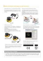
Applications Intrusion Detection New convenient and easy-to-use functions Reference Boundary Monitoring function supports intrusion detection without physically blocking the entrance. Replacable sensor, no reprogramming needed Reference Boundary Monitoring function No reprogramming needed, the configuration is stored in the I/O block. Replacing a damaged sensor is fast and easy. The OS32C constantly monitors reference points and turns OFF the safety outputs when a shift in its position is detected. Supports various operation patterns by switching zone sets. Arm detection can also be made possible...
Open the catalog to page 5
Safety Laser Scanner OS32C Compact (104.5 mm), lightweight (1.3 kg) and easy-to-install Safety Laser Scanner • Type 3 Safety Laser Scanner complies with IEC61496-1/-3. • 70 sets of safety zone and warning zone combinations are available, supporting complicated changes in working environments. • A safety radius up to 3 m and warning zone(s) radius up to 10 m can be set. • The minimum object resolution can be changed to 30, 40, 50 or 70 mm. • Provides a safety circuit of PLd/Safety Category 3 (ISO13849-1) without a dedicated controller. • The response time is configurable from 80 ms to a maximum...
Open the catalog to page 6
OS32C Mounting Brackets Appearance Description Bottom/side mounting bracket XY axis rotation mounting bracket Model OS32C-BKT1 OS32C-BKT2 Remarks Bottom/side mounting bracket x 1, unit mounting screws x 4 sets XY axis rotation mounting bracket x 1, unit mounting screws x 6 sets, bracket mounting screws x 1 set (must be used with OS32C-BKT1) Simple mounting bracket OS32C-BKT3 Protective cover for window Simple mounting brackets x 2, unit mounting screws x 4 sets * OS32C-BKT4 Mounting stand OS32C-MT Hardware kit for mounting stand OS32C-HDT When using a mounting stand, use an OS32C with side location...
Open the catalog to page 7
*1. An additional measurement error may need to be added due to reflective backgrounds. *2. For power source specification, refer to "Safety Precaution^' on page 16. *3. Rated current of OS32C is 1.025 A max. (OS32C 210 mA + OSSD A load + OSSD B load + Auxiliary output load + Warning output load + Functional Inputs). Where functional inputs are: EDM input... 50 mA Start input... 20 mA Standby input... 5 mA Zone X input... 5 mA x 8 (eight zone set select inputs) *4. Output voltage is Input voltage - 2.0 VDC. *5. Total consumption current of 2 OSSDs, auxiliary output, and warning output must not...
Open the catalog to page 8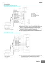
OS32C Connection Basic connection with single OS32C unit Performance Level d/Safety Category 3 (ISO13849-1) E1 PE 0V Functional Earth (Green) +24V 24VDC (White) 0VDC (Brown) S3 Standby input (Violet) Zone Select 1 (Orange/White) *4 S2 Zone Select 2 (Orange/Black) *4 S2 Zone Select 3 (Gray) *4 S2 Zone Select 4 (Pink) *4 S2 Zone Select 5 (White/Black) *4 S2 Zone Select 6 (Tan) *4 S2 Zone Select 7 (Orange) *4 S2 Zone Select 8 (Blue/White) *4 S2 Start (Black) *3 S1 Auxiliary output (Blue) Warning output (Red/Black) S1 : Start Input S2 : Zone Select Switch S3 : Standby Switch ED1, ED2: Forced guided...
Open the catalog to page 9
OS32C Connecting to the Controller G9SA-301 Performance Level d/Safety Category 3 (ISO13849-1) E1 PE 0V +24V Functional Earth (Green) 24VDC (White) 0VDC (Brown) S4 Standby input (Violet) Zone Select 1 (Orange/White) *4 S2 Zone Select 2 (Orange/Balck) *4 S2 Zone Select 3 (Gray) *4 S2 Zone Select 4 (Pink) *4 S2 Zone Select 5 (White/Black) *4 S2 Zone Select 6 (Tan) *4 S2 Zone Select 7 (Orange) *4 S2 Zone Select 8 (Blue/White) *4 S2 PLC IN1 IN2 OUT *2 Start (Black) S1 Auxiliary output (Blue) Warning output (Red/Black) EDM (Brown/White) *3 Safety output B (Yellow) Safety output A (Red) ED3 *1 ED1...
Open the catalog to page 10
OS32C System Components and Functions Main Unit (10) (9) (11) (8) (7) (6) (12) (13) (5) (1) (2) Number (3) (4) Component Function (1) RUN indicator (green) Will turn ON when safety zone is clear and OSSDs are ON. (2) Interlock Indicator (yellow) Will turn ON when in interlock state, blink under lockout, and blink in case of a failure. (3) Status/Diagnostic Display The scanner status, configuration/operation, or failure is displayed. (4) Warning Output Indicator (orange) Will turn ON when the warning output is ON. (5) STOP indicator (red) Will turn ON when safety zone is blocked, OSSD are OFF...
Open the catalog to page 11All OMRON catalogs and technical brochures
 D4F
D4F8 Pages
 D4GS-N
11 Pages
 E4E2
E4E25 Pages
 Fiber SensorBest Selection Catalog
104 Pages
 Fiber Unit E32-LT/LD
4 Pages
 G9SE Series
20 Pages
 NX-SL/SI/SO
20 Pages
 G9SP
G9SP28 Pages
 G9SX-SM
24 Pages
 G9SX-SM/LM
9 Pages
 G9SX/G9SX-GS
49 Pages
 G9SX-LM
28 Pages
 G9SB
G9SB10 Pages
 G9SA
G9SA16 Pages
 DST1 Series
5 Pages
 WS02-CFSC1-E
3 Pages
 G9SA-300-SC
9 Pages
 K8AK-AS
12 Pages
 K8AK-AW
16 Pages
 K8AK-VS
12 Pages
 K8AK-VW
12 Pages
 K8AK-PH
12 Pages
 K8DS-PH
12 Pages
 K8AK-PM
16 Pages
 K8DS-PM
12 Pages
 K8AK-PA
12 Pages
 K8DS-PA
12 Pages
 K8AK-PW
12 Pages
 K8DS-PU
12 Pages
 K8DS-PZ
12 Pages
 K8AK-TS/PT
12 Pages
 K8AK-LS
12 Pages
 K8AK-TH
12 Pages
 K2CM
K2CM16 Pages
 SE
SE15 Pages
 SAO
SAO13 Pages
 APR-S
APR-S6 Pages
 XS5
XS525 Pages
 XS2
XS229 Pages
 F92A
F92A4 Pages
 GLS
GLS3 Pages
 TL-L
TL-L5 Pages
 V680 series
68 Pages
 V680S Series
68 Pages
 MY
MY35 Pages
 E3NC-L/-S
16 Pages
 61F-GPN-BT / -BC
5 Pages
 NE1A-SCPU Series
8 Pages
![NE1A-SCPU0[]-EIP](https://img.directindustry.com/pdf/repository_di/15954/ne1a-scpu0-eip-616667_1mg.jpg) NE1A-SCPU0[]-EIP
NE1A-SCPU0[]-EIP8 Pages
 NE0A-SCPU01
6 Pages
 LY
LY14 Pages
![G2R-[]-S](https://img.directindustry.com/pdf/repository_di/15954/g2r-s-616653_1mg.jpg) G2R-[]-S
G2R-[]-S11 Pages
 G7T
G7T7 Pages
 G2A
G2A9 Pages
 G2A-434
7 Pages
 G2AK
G2AK7 Pages
 MK-S
MK-S9 Pages
 MK-S(X)
12 Pages
 MM
MM17 Pages
 MMK
MMK14 Pages
 G4Q
G4Q6 Pages
 G7Z
G7Z9 Pages
 G7J
G7J10 Pages
 E4B
E4B12 Pages
 E4A-3K
9 Pages
 E4C-UDA
5 Pages
 E6H-C
E6H-C5 Pages
 E6F-C
E6F-C5 Pages
 E6D-C
E6D-C5 Pages
 E6B2-C
5 Pages
 E6A2-C
5 Pages
 NL
NL8 Pages
 VB
VB5 Pages
 SC
SC5 Pages
 D5F
D5F5 Pages
 D5A
D5A8 Pages
 E3S-GS3E4
3 Pages
 E3S-R
E3S-R11 Pages
 E3S-A
E3S-A21 Pages
 E3S-CL
9 Pages
 E3ZM-C
14 Pages
 E3T Data Sheet
26 Pages
 E3T Series
6 Pages
 G5 Series
59 Pages
 Sysmac Catalog
410 Pages
 VT-X700
6 Pages
 E5AC-T
8 Pages
 CP1
CP112 Pages
 CP1E
CP1E12 Pages
 MS4800
40 Pages
 VC-DL100
6 Pages
 FZ4 Series
42 Pages
 ZG2
ZG216 Pages
 ZS Series
32 Pages
 ZW Series
24 Pages
 E9NC-T
2 Pages
 Vision System FH series
54 Pages
 CompoNet
28 Pages
 F3SJ Series Safety Light Curtain
108 Pages
 Code Reader/OCR
24 Pages
 Fiber Sensor Best Selection Catalog
100 Pages
 Portable Multi-logger ZR-RX70
12 Pages
 Air Particle Sensor ZN-PD-S
2 Pages
 NT series
18 Pages
 Round Water-resistant Connectors
31 Pages
 Safety Controller G9SP
28 Pages
 E3FA PHOTOELECTRIC SENSORS
24 Pages
 Switch Mode Power Supply S8VK-G
22 Pages
 Data Logger ZR-RX Series
12 Pages
 Programmable Terminals NS Series
57 Pages
 DeviceNet Safety System
30 Pages
 Switching Power Supplies
16 Pages
 Photomicro Sensors
7 Pages
 Displacement Sensors
4 Pages
 R87F / R87T AC Axial Fans
28 Pages
 H8PS Cam Positioner
32 Pages
 FQ Vision Sensor
17 Pages
 ZN-PD Air Particle Sensor
16 Pages
 S8EX Switch Mode Power Supply
24 Pages
 CP1L CP series CP1L CPU Unit
36 Pages
 E2EF
E2EF8 Pages
 FQ2 Smart camera
24 Pages


Archived catalogs
 REGULATION SOLUTIONS
24 Pages
 Sensor Accessories
38 Pages
 SMART REMOTE I/O
12 Pages
 SAFETY APPLICATION HANDBOOK
55 Pages
 Vision Systems
20 Pages
- SARRALLE industrial robot
- Digital I/O
- Single-pole switch
- IO module
- Propeller fan
- Push-button switch
- SARRALLE air circulation fan
- Digital temperature control
- SARRALLE industrial fan
- Terminal box
- Switching relay
- Analog I/O
- SARRALLE digital indicator
- Digital IO module
- SARRALLE handling robot
- SARRALLE 3D software
- AC fan
- SARRALLE interface software
- SARRALLE panel-mount indicator
- SARRALLE simulation software