NE0A-SCPU01
1 /6Pages

NE0A-SCPU01
1 /6Pages
Catalog excerpts
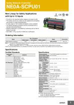
Safety Network Controller New Lineup for Safety Applications with Up to 12 Inputs • Circuits for the required safety category are easy to build. • The safety circuits you create can be registered as templates and reused, for easy standardization. • A wide range of TÜV-certified templates is also available. • The NE0A operating conditions can be monitored from a standard DeviceNet Master. • Network distribution is possible by combining with an NE1A Safety Controller. • ISO13849-1 (PLe) and IEC 61508 SIL3 certification. Ordering Information Name No. of I/O points Safety inputs Test outputs Safety outputs Unit version Safety Network Controllers 12 * 2 6 NE0A-SCPU01 Ver. 1.0 Note: 1. The standard NE0A Safety Network Controller is equipped with spring-cage terminal blocks, but screw terminal blocks are available if desired, e.g., to replace previous terminals. 2. Network Configurator version 2.1@ or higher must be used when using a NE0A-SCPU01 Safety Network Controller. * When using the NE0A-SCPU01 as a standalone Controller, one input each is required for the feedback input and manual restart. Specifications Certified Standards Certification body Specifications Standard Communications 11 to 25 VDC supplied via communicapower supply voltage tions connector Internal circuit power supply voltage (V0) *1 I/O power supply voltage (V1, V2) *1 Communications power supply Current Internal circoncuit power sumpsupply tion I/O power supply *2 Overvoltage category II Noise immunity Vibration resistance Shock resistance Mounting method Ambient operating temperature Ambient operating humidity Ambient storage tem−40 to 70°C perature Degree of protection *1. V0-G0: Internal control circuit V1-G1: For external input device, test output V2-G2: For external output device *2. Not including power consumption for external devices.
Open the catalog to page 1
NE0A-SCPU01 Safety Input Specifications Test Output Specifications Input type Output type 11 VDC min. between each terminal and ground 5 VDC max. between each terminal and ground Rated output current 1.2 V max. between each output terminal and V1 Input current Safety Output Specifications Output type Rated output current 1.2 V max. between each output terminal and V2 DeviceNet Communications Specifications Communications protocol DeviceNet compliant Connection form Multi-drop system and T-branch system can be combined (for trunk line and branch lines) Communications speed Communications media...
Open the catalog to page 2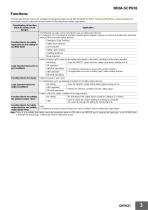
Functions The following function blocks are available for designing safety circuits with the NE0A-SCPU01. These function blocks can be selected and assembled using the interactive wizard format to efficiently design safety applications. Classification of function block for safety circuit designs Application The following six parts can be selected for use as safety input devices. For Category 3 or 4 compliance, the filter monitoring time between signals can also be adjusted with redundant wiring for the necessary safety devices. Function blocks for safety input devices and setting input filter...
Open the catalog to page 3
Internal Circuit Diagrams DC-DC Converter (Non-insulated) V+ DeviceNet Physical Layer G1 T0 T1 IN0 Safety Input Circuit Test Output Circuit Internal Circuit DC-DC Converter (Non-insulated) Safety Output Circuit Terminal name Description Power supply terminal for internal circuit (24 VDC) Power supply terminal for external input device and test output (24 VDC) Power supply terminal for external output device (24 VDC) Safety input terminal Terminals IN10 and IN11 are used only for connecting a reset switch or EDM feedback. Test output terminal Connected to IN0 to IN11 safety inputs. T0 and T1 output...
Open the catalog to page 4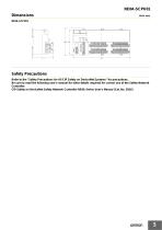
Safety Precautions Refer to the "Safety Precautions for All CIP Safety on DeviceNet Systems" for precautions. Be sure to read the following user's manual for other details required for correct use of the Safety Network Controller. CIP Safety on DeviceNet Safety Network Controller NE0A Series User's Manual (Cat. No. Z916)
Open the catalog to page 5
Terms and Conditions Agreement Read and understand this catalog. Please read and understand this catalog before purchasing the products. Please consult your OMRON representative if you have any questions or comments. Warranties. (a) Exclusive Warranty. Omron’s exclusive warranty is that the Products will be free from defects in materials and workmanship for a period of twelve months from the date of sale by Omron (or such other period expressed in writing by Omron). Omron disclaims all other warranties, express or implied. (b) Limitations. OMRON MAKES NO WARRANTY OR REPRESENTATION, EXPRESS OR...
Open the catalog to page 6All OMRON catalogs and technical brochures
 D4F
D4F8 Pages
 D4GS-N
11 Pages
 E4E2
E4E25 Pages
 Fiber SensorBest Selection Catalog
104 Pages
 Fiber Unit E32-LT/LD
4 Pages
 G9SE Series
20 Pages
 NX-SL/SI/SO
20 Pages
 G9SP
G9SP28 Pages
 G9SX-SM
24 Pages
 G9SX-SM/LM
9 Pages
 G9SX/G9SX-GS
49 Pages
 G9SX-LM
28 Pages
 G9SB
G9SB10 Pages
 G9SA
G9SA16 Pages
 DST1 Series
5 Pages
 WS02-CFSC1-E
3 Pages
 G9SA-300-SC
9 Pages
 K8AK-AS
12 Pages
 K8AK-AW
16 Pages
 K8AK-VS
12 Pages
 K8AK-VW
12 Pages
 K8AK-PH
12 Pages
 K8DS-PH
12 Pages
 K8AK-PM
16 Pages
 K8DS-PM
12 Pages
 K8AK-PA
12 Pages
 K8DS-PA
12 Pages
 K8AK-PW
12 Pages
 K8DS-PU
12 Pages
 K8DS-PZ
12 Pages
 K8AK-TS/PT
12 Pages
 K8AK-LS
12 Pages
 K8AK-TH
12 Pages
 K2CM
K2CM16 Pages
 SE
SE15 Pages
 SAO
SAO13 Pages
 APR-S
APR-S6 Pages
 XS5
XS525 Pages
 XS2
XS229 Pages
 F92A
F92A4 Pages
 GLS
GLS3 Pages
 TL-L
TL-L5 Pages
 V680 series
68 Pages
 V680S Series
68 Pages
 MY
MY35 Pages
 E3NC-L/-S
16 Pages
 61F-GPN-BT / -BC
5 Pages
 NE1A-SCPU Series
8 Pages
![NE1A-SCPU0[]-EIP](https://img.directindustry.com/pdf/repository_di/15954/ne1a-scpu0-eip-616667_1mg.jpg) NE1A-SCPU0[]-EIP
NE1A-SCPU0[]-EIP8 Pages
 LY
LY14 Pages
![G2R-[]-S](https://img.directindustry.com/pdf/repository_di/15954/g2r-s-616653_1mg.jpg) G2R-[]-S
G2R-[]-S11 Pages
 G7T
G7T7 Pages
 G2A
G2A9 Pages
 G2A-434
7 Pages
 G2AK
G2AK7 Pages
 MK-S
MK-S9 Pages
 MK-S(X)
12 Pages
 MM
MM17 Pages
 MMK
MMK14 Pages
 G4Q
G4Q6 Pages
 G7Z
G7Z9 Pages
 G7J
G7J10 Pages
 E4B
E4B12 Pages
 E4A-3K
9 Pages
 E4C-UDA
5 Pages
 E6H-C
E6H-C5 Pages
 E6F-C
E6F-C5 Pages
 E6D-C
E6D-C5 Pages
 E6B2-C
5 Pages
 E6A2-C
5 Pages
 NL
NL8 Pages
 VB
VB5 Pages
 SC
SC5 Pages
 D5F
D5F5 Pages
 D5A
D5A8 Pages
 E3S-GS3E4
3 Pages
 E3S-R
E3S-R11 Pages
 E3S-A
E3S-A21 Pages
 E3S-CL
9 Pages
 E3ZM-C
14 Pages
 E3T Data Sheet
26 Pages
 E3T Series
6 Pages
 G5 Series
59 Pages
 Sysmac Catalog
410 Pages
 VT-X700
6 Pages
 E5AC-T
8 Pages
 CP1
CP112 Pages
 CP1E
CP1E12 Pages
 MS4800
40 Pages
 VC-DL100
6 Pages
 FZ4 Series
42 Pages
 ZG2
ZG216 Pages
 ZS Series
32 Pages
 ZW Series
24 Pages
 E9NC-T
2 Pages
 Vision System FH series
54 Pages
 CompoNet
28 Pages
 F3SJ Series Safety Light Curtain
108 Pages
 Code Reader/OCR
24 Pages
 Fiber Sensor Best Selection Catalog
100 Pages
 Portable Multi-logger ZR-RX70
12 Pages
 Air Particle Sensor ZN-PD-S
2 Pages
 NT series
18 Pages
 Round Water-resistant Connectors
31 Pages
 Safety Controller G9SP
28 Pages
 E3FA PHOTOELECTRIC SENSORS
24 Pages
 Switch Mode Power Supply S8VK-G
22 Pages
 Data Logger ZR-RX Series
12 Pages
 Programmable Terminals NS Series
57 Pages
 DeviceNet Safety System
30 Pages
 Switching Power Supplies
16 Pages
 Photomicro Sensors
7 Pages
 Displacement Sensors
4 Pages
 R87F / R87T AC Axial Fans
28 Pages
 H8PS Cam Positioner
32 Pages
 OS32C Safety Laser Scanner
24 Pages
 FQ Vision Sensor
17 Pages
 ZN-PD Air Particle Sensor
16 Pages
 S8EX Switch Mode Power Supply
24 Pages
 CP1L CP series CP1L CPU Unit
36 Pages
 E2EF
E2EF8 Pages
 FQ2 Smart camera
24 Pages


Archived catalogs
 REGULATION SOLUTIONS
24 Pages
 Sensor Accessories
38 Pages
 SMART REMOTE I/O
12 Pages
 SAFETY APPLICATION HANDBOOK
55 Pages
 Vision Systems
20 Pages
- SARRALLE industrial robot
- Digital I/O
- Single-pole switch
- IO module
- Propeller fan
- Push-button switch
- SARRALLE air circulation fan
- Digital temperature control
- SARRALLE industrial fan
- Terminal box
- Switching relay
- Analog I/O
- SARRALLE digital indicator
- Digital IO module
- SARRALLE handling robot
- SARRALLE 3D software
- AC fan
- SARRALLE interface software
- SARRALLE panel-mount indicator
- SARRALLE simulation software